OM-1076-001.pdf - 第81页
B01 Shape Data (B01_07) 0107-001 2-57 Tg0502-PM-CL The coordinate system is as follows. Example: When "Back Ltg" is set for "Ligting System": Regard the shade section as "dark" and the secti…
B01 Shape Data (B01_07)
0206-002 2-56 Tg0502-PM-CL
(2) Stg Coord X [mm], Y [mm]
Set the start position (coordinates X and Y) of the selected linear edge
in each data box.
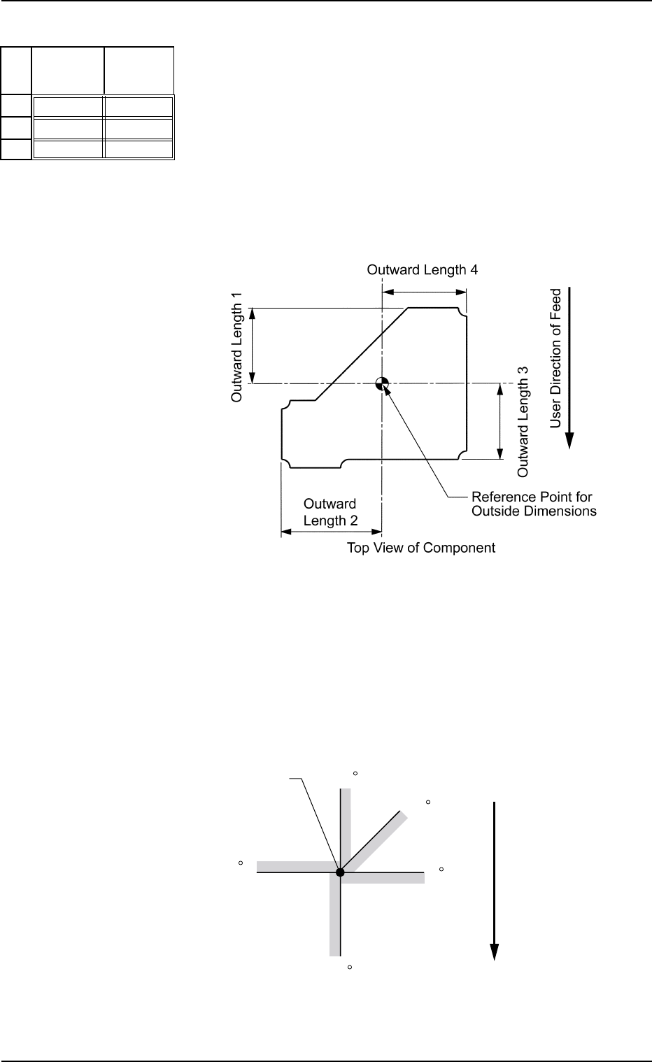
Enter the distance from the reference position determined by the pa-
rameters in the "1", "2", "3", and "4" data boxes of the label "Outward
Length" (described in "Outward Length 1, 2, 3, 4").
Unit: mm
Data Input Range:
Xn: −99.999 to +99.999
Yn: −99.999 to +99.999
Fig.B115
Stg Coord
Y [mm]
+00.000
+00.000
+00.000
Stg Coord
X [mm]
+00.000
+00.000
+00.000
No
1
2
3
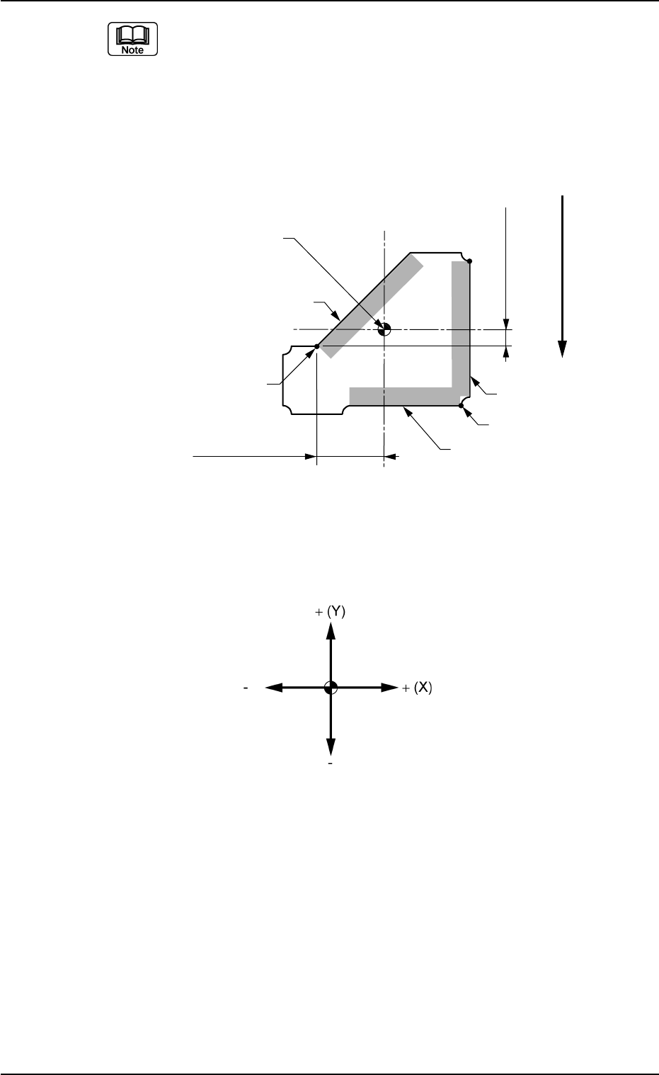
• Definition of Start Position (Coordinates X and Y)
The start position (coordinates X and Y) is determined according to
the selection of the lighting system ("Back Ltg" or "Front Ltg"), and
the brightness at both sides of set edges.
See the figure below for your reference and determine the start po-
sition (coordinates X and Y).
Straight Lines: Linear Edges
Fig. B116
Fig. B117
90
45
0
180
270
Start Position
Top View
User Direction of Feed
B01 Shape Data (B01_07)
0107-001 2-57 Tg0502-PM-CL
The coordinate system is as follows.
Example:
When "Back Ltg" is set for "Ligting System":
Regard the shade section as "dark" and the section without shade as
"bright" for the set linear edges.
When "Front Ltg" is set for "Ligting System":
Regard the shade section as "bright" and the section without shade as
"dark" for the set linear edges.
Start Position X1
Start Position Y1
User direction of Feed
Start Position(X2, Y2)
Start Position
(X1, Y1)
Edge 3
Edge 2
Edge 1
Top View of Component
Reference Point for
Outside Dimensions
Fig. B118
Fig. B119
B01 Shape Data (B01_07)
0107-001 2-58 Tg0502-PM-CL
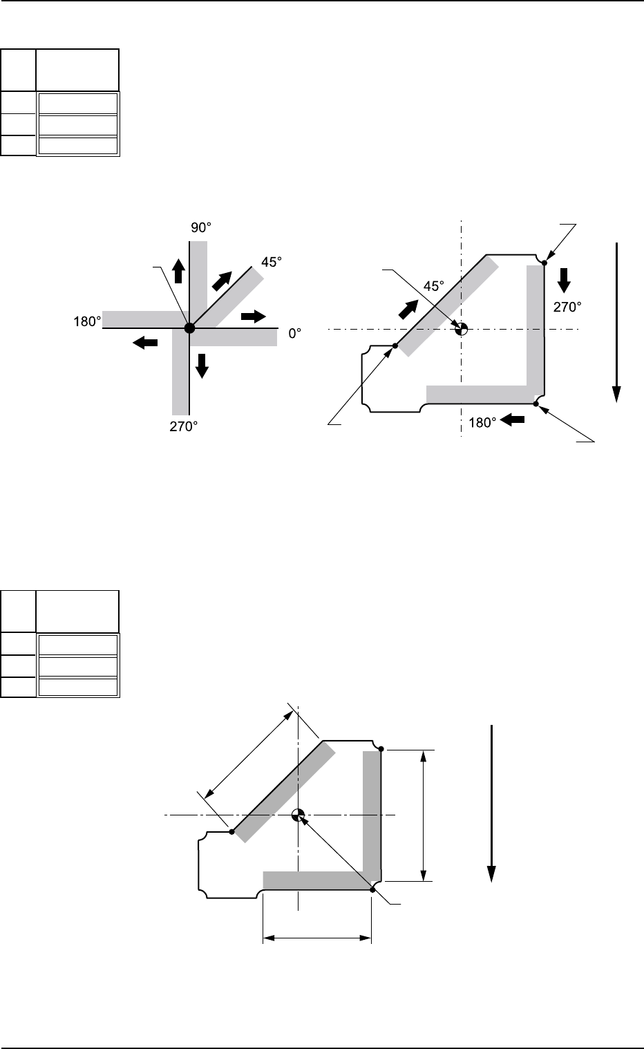
(3) Direction [°]
Set the direction of the selected linear edge in the pertinent data box.
Check in which directions the linear edges are extending from the
start position and enter the directions.
Unit: ° (degree)
Data Input Range: 0 to 359
Fig. B120
Direction
[°]
000
000
000
No
1
2
3
Start Position
Start Position
Start Position
Start Position
Relation between Start Position
and Directions
Example of Direction Setting
Start Position
(X3, Y3)
Top View
User Direction of Feed
(4) Width [mm]
Set the width of the selected linear edge in the pertinent data box.
Unit: mm
Data Input Range: 0.01 to 99.99
Fig. B122
Width
[mm]
00.01
00.01
00.01
No
1
2
3
Linear Edge
Width 3
Linear Edge
Width 2
Linear Edge
Width 1
Top View of Component
User Direction of Feed
Reference Point for
Outside Dimensions
Fig. B121
Fig. B123