YSP10_Mainte_E.pdf - 第118页
1.Specication A-2 Appendix 1.2 Power connection terminals Open the lower front panel to locate the power connection terminals. Connect the po wer cable leads as shown below to the primary side terminal of the main brea…
1.Specication
A-1
Appendix
1. Specification
1.1 Air regulator unit
1.1.1 Supply air pressure
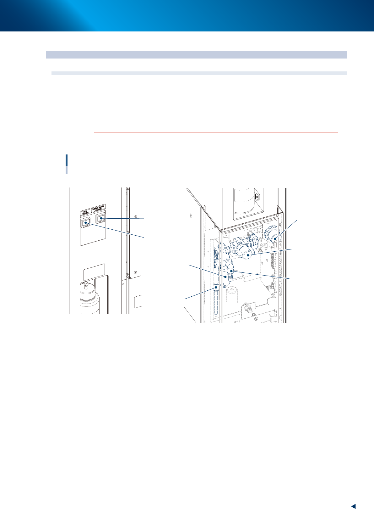
The air regulator unit, which adjusts the air pressure to supply air to the air-driven unit of this machine, is
installed inside the lower panel of the machine front side. Adjust the air pressure to the appropriate value
shown below.
c
CAUTION
Before using the air regulator, make sure that the source air pressure is at least an appropriate value (0.45MPa or higher).
Air regulator unit and air connector
Upper left part of the machine front side Lower left part of the machine front side
Air pressure supply
regulator
Air pressure supply/
shutoff switch
Source air connector
Air filter
Mist filter
Digital pressure gauge
for cleaner
Digital pressure gauge
to check the set pressure
53A01-KMJ-00
►
Digital pressure gauge
Appears set air pressure. Adjust the pressure in between the following values by pressure regulator.
Set air pressure: 0.40MPa to 0.41MPa
►
Digital pressure gauge for cleaner vacuum
Appears air pressure (negative) of cleaner.
►
Source air pressure regulator
Adjusts the source air pressure to an appropriate pressure (0.45MPa or higher). Turn the knob to adjust
the set air pressure to 0.40MPa.
►
Air pressure supply/shutoff switch
Turn this switch to the right to cut off the air supply to the machine and exhaust any remaining air in the
air hose.
►
Source air connector
Connect the air hose with an inner diameter of at least 8mm having a 30SH socket (Nitto Koki, or
equivalent) to this connector and supply compressed air to the machine. Use dry, clean air passed
through an air dryer and air filter.
1.Specication
A-2
Appendix
1.2 Power connection terminals
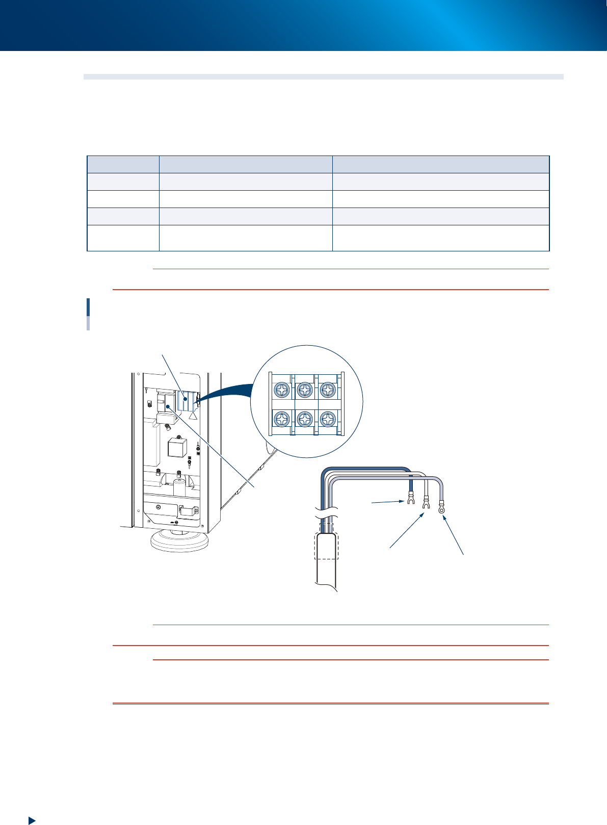
Open the lower front panel to locate the power connection terminals. Connect the power cable leads as
shown below to the primary side terminal of the main breaker (L1 and L2) and to the ground terminal of the
machine.
►
Power supply specification
Items Specification Note
Power source Single phase 200/208/220/230V +/- 20V
Frequency 50/60Hz
Power capacity 6.9kVA Except for the temperature adjustment unit (option).
Power
consumption
1.2kW
Operating the machine without peripherals/Normal
operation
c
CAUTION
When installing an electrical leakage breaker upstream, use a sensed current is 30mA or higher.
Power input terminals and cables
Lower-left part of the machine front
Power input terminals M5
Power cables
Terminal block
Main breaker
L1 L2 PE
L1
L M5
L2
N M5
L=350mm
Ring-tongue crimp terminal M5
Ground terminal (green)
53A03-KME-10
c
CAUTION
Use a power cable whose conductor cross-section area is greater than 6mm
2
.
w
WARNING
TO AVOID THE RISK OF ELECTRICAL SHOCK, MAKE SURE THAT THE EXTERNAL POWER SOURCE IS OFF BEFORE
CONNECTING THE POWER CABLE. ALSO MAKE SURE THAT THE GROUND CABLE IS SECURELY CONNECTED TO THE
MACHINE.
1.Specication
A-3
Appendix
1.3 Connection between machines
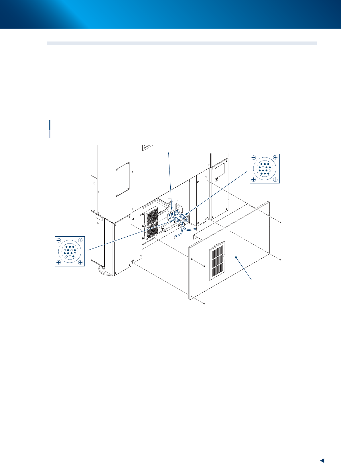
To exchange signals such as board request and operation status with the downstream or upstream machine,
the "NEXT INTERFACE" and "PREVIOUS INTERFACE" connectors in the lower panel on the rear of the
machine are used.
The "NEXT INTERFACE" connector connects to the downstream machine, and the "PREVIOUS INTERFACE"
connector connects to the upstream machine such as a loader.
On the left part of the rear side of the machine, of standard "right to left" flow type, PREVIOUS INTERFACE
is on the left side and NEXT INTERFACE on the right. These two connectors adopt AMP 206043-1 (14-pin
receptacle).
Connection between machines
Lower panel on the rear side
NEXT
Interface connector
PREVIOUS
AMP 206043-1
(14-pin receptacle)
AMP 206043-1
(14-pin receptacle)
14
11
12
7
4
8
1
3
14
11
12
7
8
3
1
4
53A05-KMJ-00