YSP10_Mainte_E.pdf - 第120页
1.Specication A-4 Appendix 1.3.1 PREVIOUS INTERF ACE connector When the following three conditions are met, the PREVIOUS INTERF ACE cir cuit in the machine allo ws the next board to be carried in. • Machine is ready fo…
1.Specication
A-3
Appendix
1.3 Connection between machines
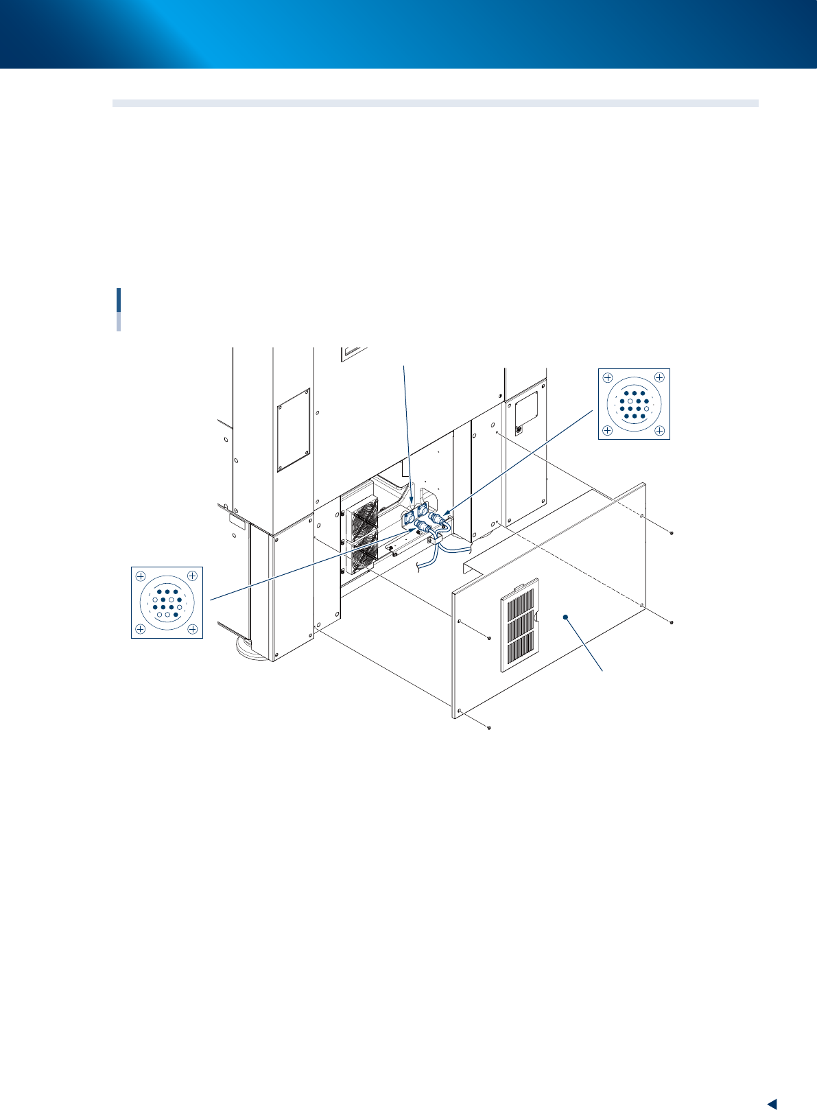
To exchange signals such as board request and operation status with the downstream or upstream machine,
the "NEXT INTERFACE" and "PREVIOUS INTERFACE" connectors in the lower panel on the rear of the
machine are used.
The "NEXT INTERFACE" connector connects to the downstream machine, and the "PREVIOUS INTERFACE"
connector connects to the upstream machine such as a loader.
On the left part of the rear side of the machine, of standard "right to left" flow type, PREVIOUS INTERFACE
is on the left side and NEXT INTERFACE on the right. These two connectors adopt AMP 206043-1 (14-pin
receptacle).
Connection between machines
Lower panel on the rear side
NEXT
Interface connector
PREVIOUS
AMP 206043-1
(14-pin receptacle)
AMP 206043-1
(14-pin receptacle)
14
11
12
7
4
8
1
3
14
11
12
7
8
3
1
4
53A05-KMJ-00
1.Specication
A-4
Appendix
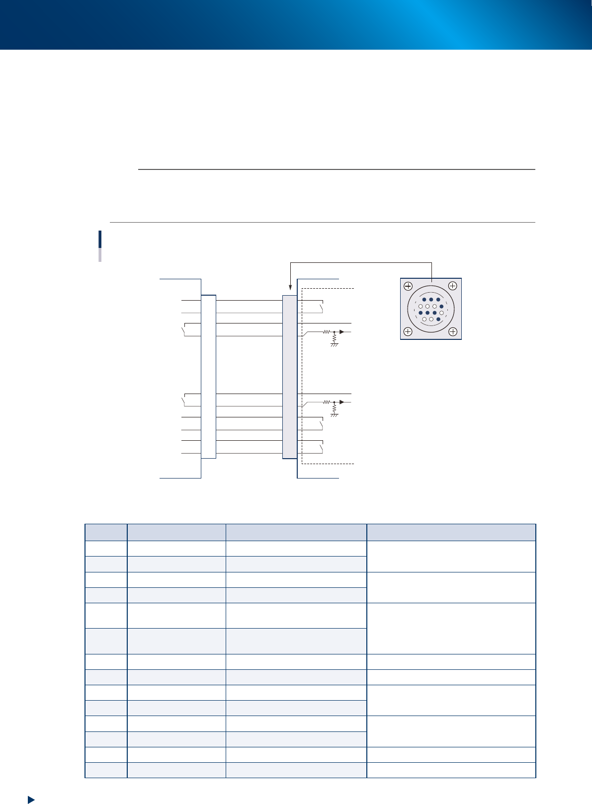
1.3.1 PREVIOUS INTERFACE connector
When the following three conditions are met, the PREVIOUS INTERFACE circuit in the machine allows the
next board to be carried in.
• Machine is ready for carrying in a board (BUSY OUT : ON)
• Board carry-in signal is input from the upstream (pre-process) machine. (BA IN : ON)
• Automatic operation signal is input from the upstream (pre-process) machine. (UR IN : ON)
n
NOTE
• When the automatic operation signal (UR IN) of the upstream machine turns off during transfer of a board, the
machine temporarily stops carrying in the board.
• When the board being carried in is detected by the entrance sensor of the machine, the BUSY OUT signal turns off.
• Carrying in the board is finished when both the BUSY OUT and BA IN turn off.
1
2
3
4
5
6
7
8
9
10
11
12
13
14
DC +24V
PNP input
DC +24V
PNP input
Input
Relay output
Relay output
Relay output
Relay output
Relay output
Input
Input
I/O BOARD
7
12
4
8
1
14
11
3
PREVIOUS INTERFACE circuit
Connection between the YSP10 and the pre-process machine.
YSP10
PREVIOUS INTERFACE
Pre-pricess machine
NEXT INTERFACE
AMP 206043-1
(14-pin receptacle)
53A06-KMJ-00
►
Board transfer signal specifications (PREVIOUS INTERFACE)
Pin No. Signal name I/O specifications Signal specifications
1 BUSY OUT (output) Relay contact (zero voltage) output
Signal output during board carry-in to the
YSP10
2 BUSY OUT (output) Relay contact (zero voltage) output
3 BA IN (com) DC +24V
Signal input when the pre-process machine
can carry-out the board.
4 BA IN (input) PNP input
5
Exclusive for fitting
specify
Prevents misinsertion.
Use for prevention of mis-connection
6
Exclusive for fitting
specify
Prevents misinsertion.
7 NC
8 NC
9 UR IN (com) DC +24V
Signal input during the automatic operation
of pre-process machine
10 UR IN (input) PNP
11 LR OUT Relay contact (zero voltage) output
Signal output during the automatic
operation of YSP10
12 LR OUT Relay contact (zero voltage) output
13 Not use
14 Not use
1.Specication
A-5
Appendix
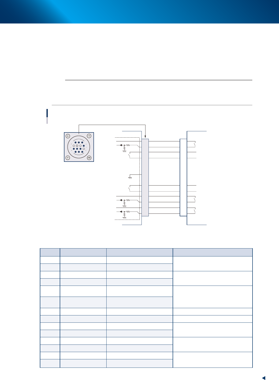
1.3.2 NEXT INTERFACE connector
When the following three conditions are met, the NEXT INTERFACE circuit in the machine allows the board
to be carried out.
• Machine is ready for carrying in a board (BA OUT : ON)
• Board carry-in signal is input from the upstream machine. (BUSY IN : ON)
• Automatic operation signal is input from the upstream machine. (LR IN : ON)
n
NOTE
• When the automatic operation signal (LR IN) from the downstream machine turns off during transfer of a board, the
machine stops temporarily carrying out the board.
• When the board being carried out is detected by the exit sensor, the BA OUT signal turns off.
• Carrying out the board is finished when both the BUSY IN and BA OUT turn off.
1
2
3
4
5
6
7
8
9
10
11
12
13
14
Relay output
Input
Input
Relay output
Relay output
14
11
12
7
4
8
3
1
NEXT INTERFACE circuit
Connection between the YSP10 and the post-process machine.
AMP 206043-1
(14-pin receptacle)
Post-process machine
PREVIOUS INTERFACE
YSP10
NEXT INTERFACE
DC +24V
PNP input
DC +24V
PNP input
DC +24V
PNP input
Relay output
Relay output
GND
I/O BOARD
53A07-KMJ-00
►
Board transfer signals specifications (NEXT INTERFACE)
Pin No. Signal name I/O specifications Signal specifications
1 BUSY IN (com) DC +24V
Signal output during board carry-in to the
post-process machine
2 BUSY IN (input) PNP input
3 BA OUT (output) Relay contact output
Signal output when the YSP10 is ready for
the board carry-out.
4 BA OUT (output) Relay contact output
5
Exclusivefortting
specify
Prevents misinsertion.
Use for prevention of mis-connection
6
Exclusivefortting
specify
Prevents misinsertion.
7 Not use
8 NC
9 UR OUT (output) Relay contact (zero voltage) output
Signal output during the automatic operation
of YSP10
10 UR OUT (output) Relay contact (zero voltage) output
11 LR IN (com) DC +24V
Signal input during the automatic operation
of post-process machine
12 LR IN (input) PNP input
13 LE IN (com) DC +24V
Signal from post-process machine during
waiting for board
(Mounter only)
14 LE IN (input) PNP input