YSP10_Mainte_E.pdf - 第122页
1.Specication A-6 Appendix 1.4 Adapted mask 1.4.1 The mask flame size and the mask standard position ► The mask flame size and the mask standard position n NOTE The size unit is mm. "A" of Y direction standar…
1.Specication
A-5
Appendix
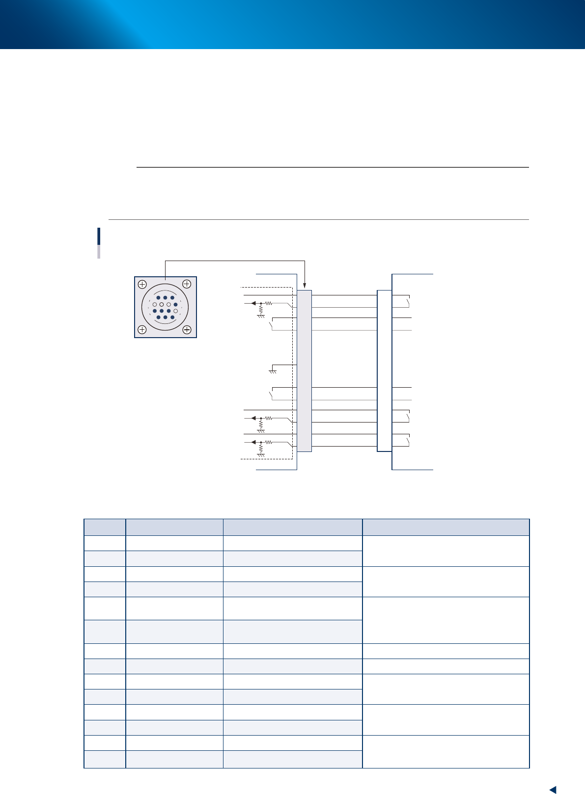
1.3.2 NEXT INTERFACE connector
When the following three conditions are met, the NEXT INTERFACE circuit in the machine allows the board
to be carried out.
• Machine is ready for carrying in a board (BA OUT : ON)
• Board carry-in signal is input from the upstream machine. (BUSY IN : ON)
• Automatic operation signal is input from the upstream machine. (LR IN : ON)
n
NOTE
• When the automatic operation signal (LR IN) from the downstream machine turns off during transfer of a board, the
machine stops temporarily carrying out the board.
• When the board being carried out is detected by the exit sensor, the BA OUT signal turns off.
• Carrying out the board is finished when both the BUSY IN and BA OUT turn off.
1
2
3
4
5
6
7
8
9
10
11
12
13
14
Relay output
Input
Input
Relay output
Relay output
14
11
12
7
4
8
3
1
NEXT INTERFACE circuit
Connection between the YSP10 and the post-process machine.
AMP 206043-1
(14-pin receptacle)
Post-process machine
PREVIOUS INTERFACE
YSP10
NEXT INTERFACE
DC +24V
PNP input
DC +24V
PNP input
DC +24V
PNP input
Relay output
Relay output
GND
I/O BOARD
53A07-KMJ-00
►
Board transfer signals specifications (NEXT INTERFACE)
Pin No. Signal name I/O specifications Signal specifications
1 BUSY IN (com) DC +24V
Signal output during board carry-in to the
post-process machine
2 BUSY IN (input) PNP input
3 BA OUT (output) Relay contact output
Signal output when the YSP10 is ready for
the board carry-out.
4 BA OUT (output) Relay contact output
5
Exclusivefortting
specify
Prevents misinsertion.
Use for prevention of mis-connection
6
Exclusivefortting
specify
Prevents misinsertion.
7 Not use
8 NC
9 UR OUT (output) Relay contact (zero voltage) output
Signal output during the automatic operation
of YSP10
10 UR OUT (output) Relay contact (zero voltage) output
11 LR IN (com) DC +24V
Signal input during the automatic operation
of post-process machine
12 LR IN (input) PNP input
13 LE IN (com) DC +24V
Signal from post-process machine during
waiting for board
(Mounter only)
14 LE IN (input) PNP input
1.Specication
A-6
Appendix
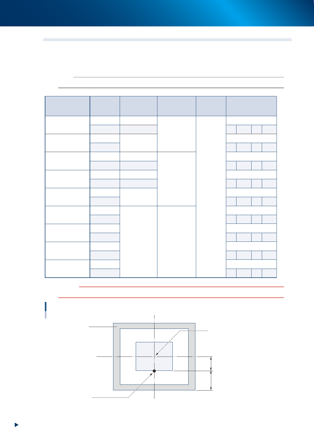
1.4 Adapted mask
1.4.1 The mask flame size and the mask standard position
►
The mask flame size and the mask standard position
n
NOTE
The size unit is mm. "A" of Y direction standard is the value from mask outer frame. "B" is the value from mask frame center.
Mask flame size
Mask
standard
position
Maximum
board size
Squeegee size
X direction
datum
Y direction datum
L750 × W750
Center L650 × W510
L620
Center
Center
Front side
L650 × W460 A 145 B 230
L750 × W650
Center
L650 × W350
Center
Front side
A 150 B 175
L750 × W750
Center L510 × W510
L530
Center
Front side L510 × W460 A 145 B 230
L736 × W736
Center L510 × W510 Center
Front side L510 × W460 A 138 B 230
L750 × W650
Center
L510 × W350
Center
Front side A 150 B 175
L650 × W550
Center
L330 × W250 L350
Center
Front side A 150 B 125
L600 × W550
Center Center
Front side A 150 B 125
L550 × W650
Center Center
Front side A 200 B 125
L584 × W584
Center Center
Front side A 167 B 125
c
CAUTION
The mask with frame size "L550 x W 650" cannot be used on L650 type machine.
When the mask standard position is "front side".
Center of mask flame
Mask
Datum position
This position is to be aligned to the center of the board front side.
A
B
53A04-KMJ-00
1.Specication
A-7
Appendix
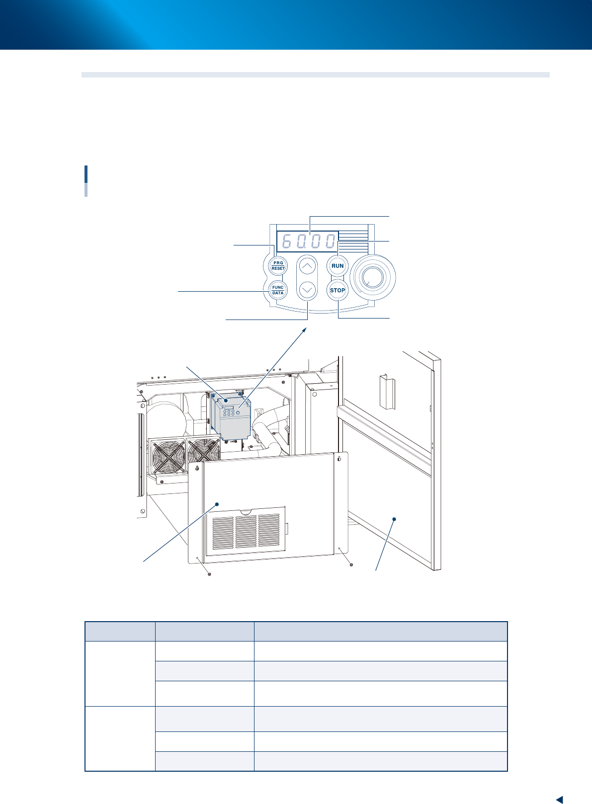
1.5 Inverter
The suction unit in the YSP10 machine uses the inverter. When the defect occurs in the inverter or the
suction motor, the error message appears on the operating display of the machine.
To check the error code displayed on the inverter, open the lower door of the front side of YSP10, remove
the inner cover as described in the illustrations below. Then the error code displayed on the LED panel can
be seen.
Inverter
For suction unit
Lower door of the front side
Inner cover (Front lower door)
Program/reset key
(See the table below)
Control panel
LED panel
Start key
Starts the motor
Select from setting items,
change the function code data etc.
Stop key
Stops the motor
Up/down key
Inverter
Function/data key
(See the table below)
53A08-KMJ-00
►
Details of the operating panel
Key name Operating mode Function description
PRG/RESET
Running mode Press this key to change to program mode.
Program mode Press this key to change to running mode.
Alarm mode
After clearing the cause of the alarm, press this key to release
the alarm and change to operating mode.
FUNC/DATA
Running mode
Switches monitors (output frequency, output current, and output
voltage etc.) on operating conditions.
Program mode Displays function code and fixes the data.
Alarm mode Displays details of alarm information.