YSP10_Mainte_E.pdf - 第125页
2. Periodic inspection check sheet A-9 Appendix 2. Periodic inspection check sheet Use the inspection check sheet to perform the periodic inspection. This check sheet contains weekly and monthly inspection items in addit…
1.Specication
A-8
Appendix
►
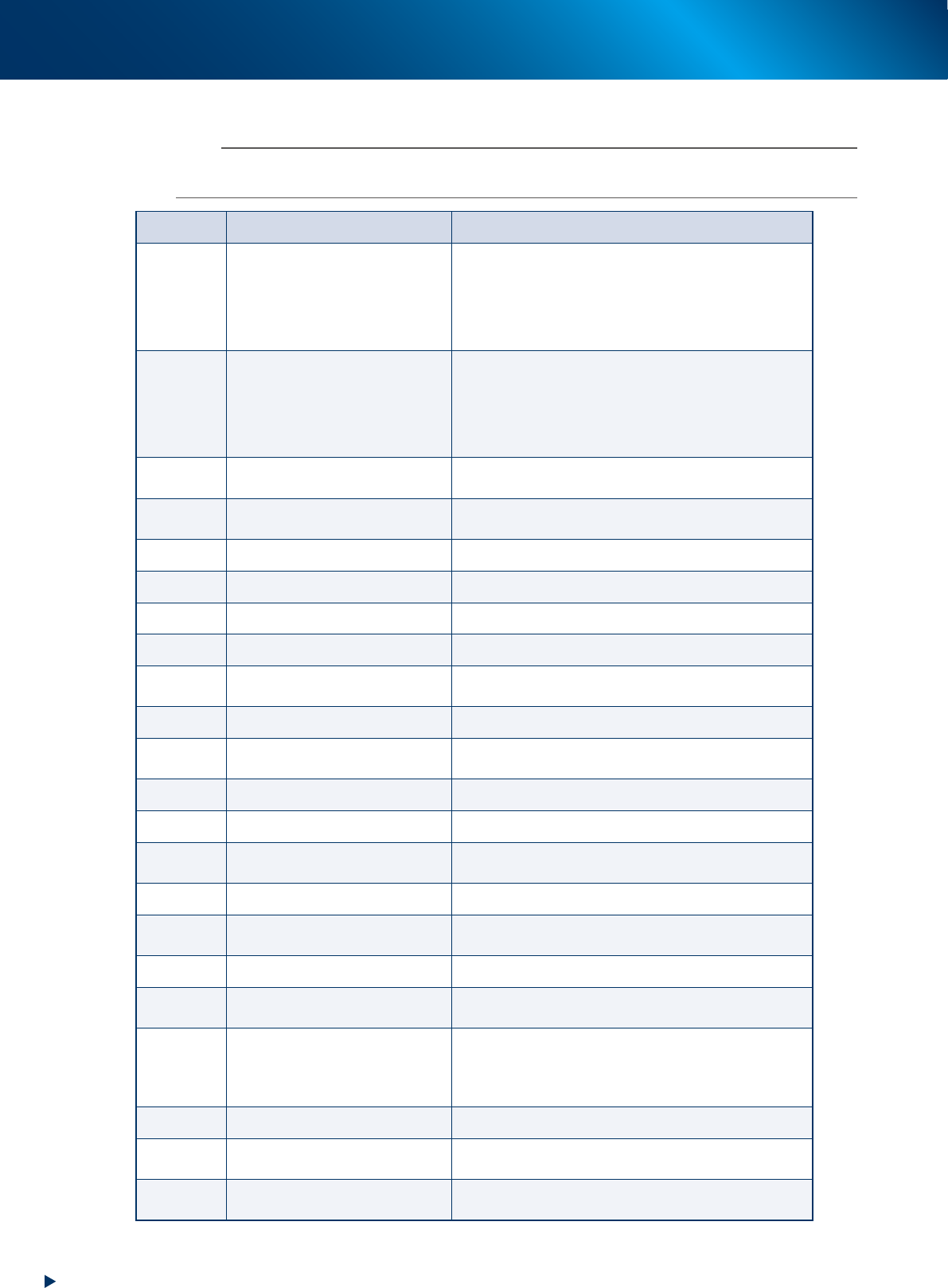
The list of inverter error code
n
NOTE
When some error occurs on the inverter, check the error code on the LED panel from the table below, contact to our sales
representatives.
Code Alarm name Case
0c1
0c2
0c3
Instant overcurrent
The instant value of the output current from the inverter
exceeds the overcurrent level.
Oc1: Overcurrent at acceleration
Oc2: Overcurrent at deceleration
Oc3: Overcurrent at fixed velocity
0u1
0u2
0u3
Overvoltage
The voltage of direct current intermediate circuit exceeds
the overvoltage detection level.
Ou1: Overvoltage at acceleration
Ou2: Overvoltage at deceleration
Ou3: Overvoltage at fixed velocity
lu
Undervoltage
The voltage of direct current intermediate circuit falls
below the undervoltage level.
lin
Input phase loss
Input phase loss, or power supplies interphases are
imbalanced largely.
0pl
Output phase loss Output phase loss occurs.
0h1
Overheat of cooling fin The temperature of the cooling fin rises.
0h2
External alarm The external alarm ("THR") is input.
0h4
Motor protection (PTC thermistor) The temperature of the motor get overheated.
0h6
Overheat of charging resistor
The internal charging resistor of the inverter get
overheated.
dbh
Overheat of braking resistor The thermal function for the braking resistor is actuated.
0l1/0l2
Overload of motor 1 / Overload of
motor 2
The electric thermal function for the motor 1 / motor 2,
which detects the overload of the motor, is actuated.
0lu
Overload of the inverter The temperature inside the inverter is overheated.
er1
Memory error It occurs some trouble (e.g. data writing error).
er2
Connection error of the touch
panel
The connection error occurs between the remote touch
panel (option) and the inverter.
er3
CPU error It occurs some trouble at CPU (e.g. runaway).
er6
Operation error
The wrong operation against the operating method
causes an error.
er7
Tuning error Failure of the auto tuning
er8
RS-485 communication error
The communication error occurs at RS-485
communication.
erf
Data save error by undervoltage
The commands which are set using touch panel like
frequency command, PID process command, timer
operating period, and "UP"/"DOWN" signals cannot be
saved correctly at the machine shutdown.
err
Simulated breakdown The "err" massage appears.
cof
Disconnection of PID feedback
wire detected
The signal wire of PID feedback is broken.
erd
Step-out detected (For driving
synchronous motor)
The step-out of the synchronous motor detected

2. Periodic inspection check sheet
A-9
Appendix
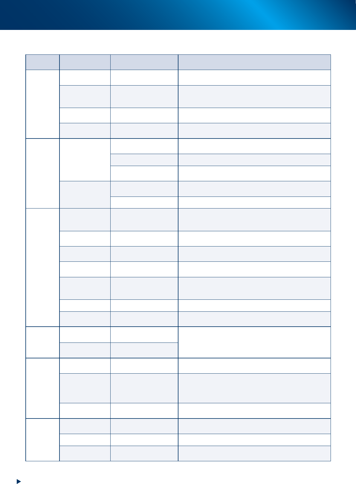
2. Periodic inspection check sheet
Use the inspection check sheet to perform the periodic inspection.
This check sheet contains weekly and monthly inspection items in addition to "daily inspection" items.
Copy and use the "Inspection check sheet (sample)" on the next page, or prepare and practice the format
like this check sheet.
█
Points for the inspection
►
The periodic inspection should be performed by the engineer who have completed YAMAHA
maintenance training, or under the instruction of that engineer.
►
Before greasing up, perform warm-up operation and wipe off the excess grease.
2. Periodic inspection check sheet
A-10
Appendix
►
Inspection check sheet
Section Items Subject Operation Weekly (mm/dd)
Monthly
(Cleaning)
Monthly
(Lubrication)
Note
Printing
head
SY-axis
Ball screw
Guide
• Is not there any solder adhesion.
*Dispense grease and wipe off the extra amount by condition.
/ / / / / / / / /
SZ-axis
Ball screw
Guide
Shaft guide
• Is not there any solder adhesion.
*Dispense grease and wipe off the extra amount by condition. / / / / / / / / /
Squeegee Scraping unit
• No wound, chip or wearing on the scraping unit.
• Is not there any solder adhesion.
Solder drop
prevetion plate (OP)
Solder drop prevention
plate
Is not there any solder adhesion.
/ / / / / / /
Cleaning unit
Cleaning unit
Roll paper
• Does it set correctly.
• Is the roll paper wound-up rightly.
/ / / / / / /
Head unit condition
Is not soiled the cleaner head.
/ / / / / / /
Y direction guide
• Is not there any solder adhesion.
*Dispense grease and wipe off the extra amount by condition.
/ / / / / / / / /
Blower unit
Blower hose
* Check the cracking on the hose and replace when it wears.
• Does the cleaner head swing smoothly.
/ / / / / / /
Inner filter operation
*Clean up the dirt of filter and replace when needed.
/ / / / / / /
Conveyor
unit
Conveyor transfer
belt
Contamination or scuffing
Operation
Is there any contamination, wear, or scuffing.
*Clean up when the scuffing falls on the sensor.
*Replace the belt when needed.
/ / / / / / /
PU-axis
Ball screw
Shaft guide
• Is there any foreign object or solder adhesion.
*Apply grease and wipe off excess grease when necessary.
/ / / / / / / / /
W-axis conveyor
auto width
Ball screw guide
Hexagon spline shaft guide
• Is not there any solder adhesion.
*Dispense grease and wipe off the extra amount by condition.
/ / / / / / / / /
Edge clamp Movement and dirt
• Does it move correctly.
• Is not there any solder adhesion on the edge plate.
/ / / / / / /
Board flap Movement and dirt
• Does it move correctly.
• Is there any foreign object or solder adhesion.
*Clean up the underside of the flap.
/ / / / / / /
Matrix plate Dirt
• Is not there any foreign object or solder adhesion.
/ / / / / / /
Mask vacuum
Movement
Vacuum filter
• Check that the mask vacuum runs correctly.
*Check the filter and clean up or replace when necessary.
/ / / / / / /
X-axis,
Y-axis, and
Z-axis
X1-axis, X2-axis,
and Y-axis
Ball screw
Guide
• Is not there any solder adhesion.
*Dispense grease and wipe off the extra amount by condition.
/ / / / / / / / /
Z-axis
Ball screw
Shaft guide
/ / / / / / / / /
Recognition
unit
Mask camera
Contamination of lighting
lens
• Is there any contamination on the lighting lens.
/ / / / / / /
CX-axis and CY-axis
Ball screw
Guide
• Is not there any solder adhesion.
*Dispense grease and wipe off the extra amount by condition.
Caution: CY-axis cover should be removed upon performing the
maintenance.
/ / / / / / / / /
Board camera
Lighting unit
Half mirror
Is not soiled the lighting unit or half mirror.
/ / / / / / / / /
Others
Air supply unit
Air filter
Mist filter
*Clean up the filters and replace when needed.
/ /
Controller Filter
*Clean up the filters and replace when needed.
/ /
Cooling fan Filter
(Places inside the lower panel on the front/rear side)
*Clean up the filters and replace when needed.
/ / / / / / /