YSP10_Mainte_E.pdf - 第47页
Chapt er 3 P eriodic mainten ance it ems Contents 1. Before beginnin g w ork 3-1 2. Monthly maintenance 3-2 2.1 Cleaning matrix plate 3-2 2.2 Motion check of edge clamp 3-3 2.3 Mot ion check of boar d flap 3-4 2.4 Suctio…
2. The daily inspection and cleaning
2-8
Chapter 2 Daily maintenance items
2.6.2 Removable type
When the solder etc. adheres to the solder drop prevention plate, detach and clean it according to the
following procedure.
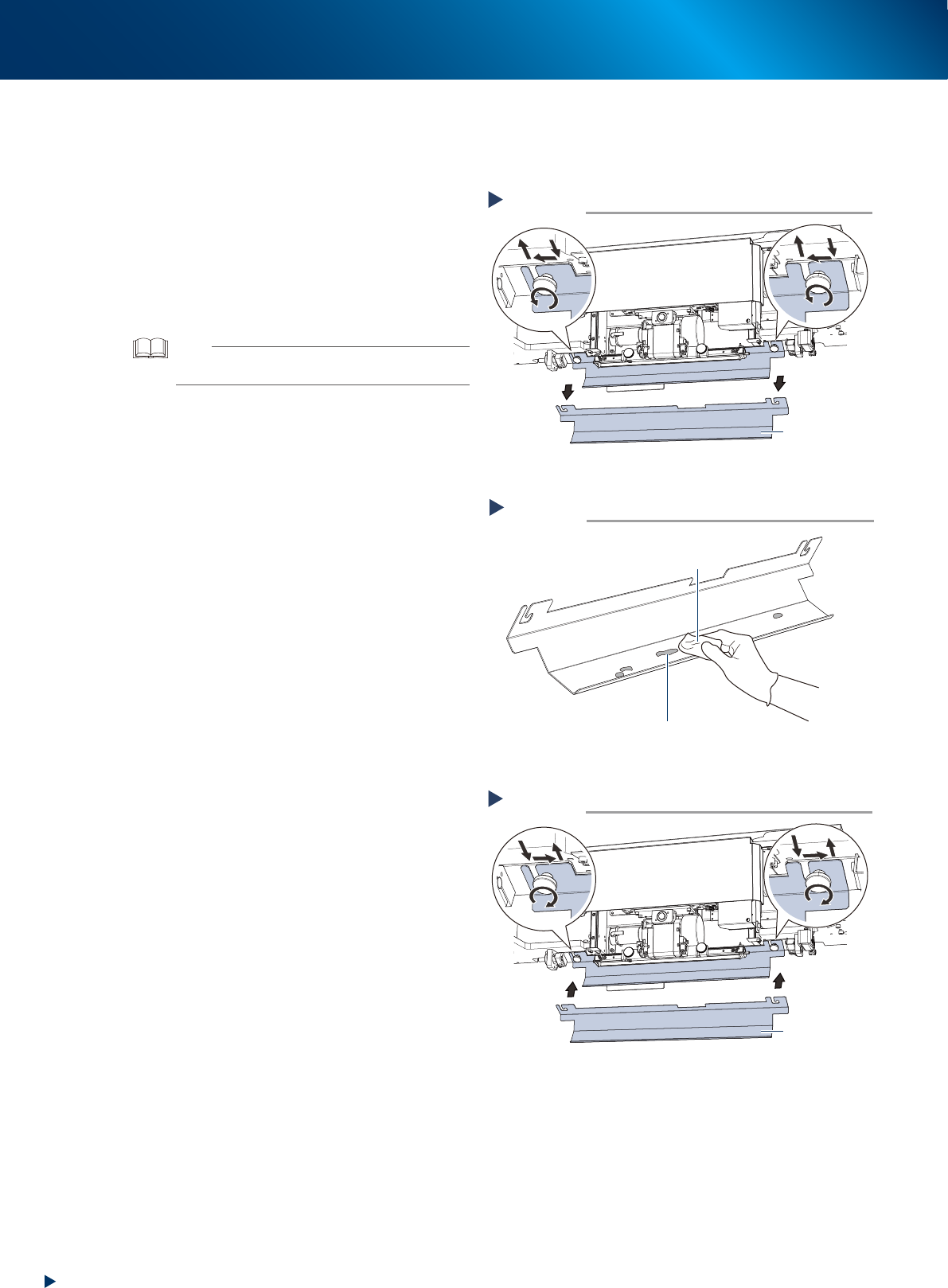
1
Detach the solder drop prevention
plate.
1. Loosen the mounting knobs of solder drop
prevention plate by turning them to
counterclockwise.
2. Detach the solder drop prevention plate from
the squeegee head as illustrated at right.
TIP
The mounting knob has non-drop mechanism upon
loosening.
2
Clean the solder drop prevention plate
by wiping out the solder adherence
with a lint-free cloth applied of a few
drops of ethanol.
3
Attach the solder drop prevention plate
to its original position.
1. Attach the solder drop prevention plate to
the squeegee head as illustrated at right.
2. Fix the solder drop prevention plate by
tightening the mounting knobs to clockwise.
Detaching solder drop prevention plate
Solder drop
prevention plate
Step 1
53211-KMJ-00
Cleaning solder drop prevention plate
Step 2
Lint-free cloth applied of
a few drops of ethanol
Solder adherence
53212-KMJ-00
Attaching solder drop prevention plate
Solder drop
prevention plate
Step 3
53213-KMJ-00

Chapter 3 Periodic maintenance items
Contents
1. Before beginning work 3-1
2. Monthly maintenance 3-2
2.1 Cleaning matrix plate 3-2
2.2 Motion check of edge clamp 3-3
2.3 Motion check of board flap 3-4
2.4 Suction unit 3-5
2.4.1 Cleaning and replacing the filter 3-5
2.4.2 Visual inspection of blower hose 3-6
2.5 CX-axis, CY-axis and cleaning unit 3-7
2.5.1 Cleaning and lubricating the CX-axis 3-7
2.5.2 Cleaning and lubricating the CY-axis and the cleaning unit 3-13
2.6 Mask holder 3-16
2.6.1 Inspection and cleaning of mask holder plate 3-16
2.7 Base unit and others 3-17
2.7.1 Inspecting and cleaning the fan filters. 3-17
2.7.2 Replacing air/oil mist filter and cleaning cup. 3-18
3. 3-month maintenance 3-21
3.1 W-axis 3-21
3.1.1 Cleaning and lubrication of W-axis 3-21
3.2 PU-axis 3-24
3.2.1 Cleaning and lubricating the PU-axis 3-24
3.3 Z-axis 3-26
3.3.1 Cleaning and lubricating the Z-axis 3-26
3.4 SY-axis 3-29
3.4.1 Cleaning and lubricating SY-axis 3-29
3.5 SZ-axis 3-31
3.5.1 Cleaning and lubricating SZ-axis 3-31
3.5.2 Cleaning and Lubricating of SZ-axis with PSC 3-35
4. 6-month maintenance 3-39
4.1 X-axis and Y-axis 3-39
4.1.1 Cleaning and lubricating for X-axis and Y-axis 3-39
1. Before beginning work
3-1
Chapter 3 Periodic maintenance items
1. Before beginning work
The maintenance procedures (such as lubrication) described in this chapter often require to insert a
part of your body into the machine. The following items should be understood in advance.
█
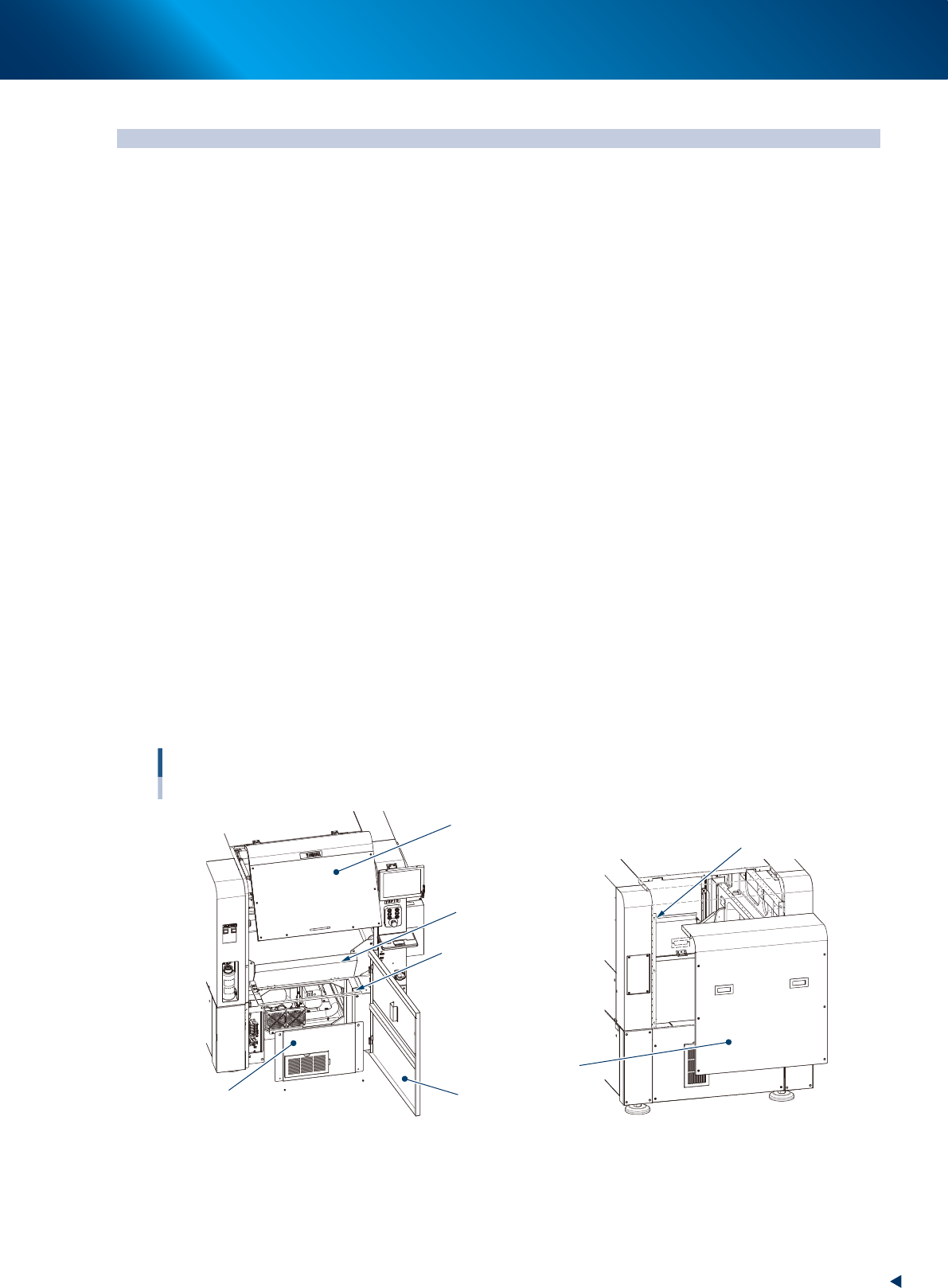
Doors and covers
The following describes the doors or covers required to open upon maintenance work.
►
Safety cover
This is a safety cover which is opened and closed frequently during maintenance work or setting up..
When the cover is opened during operation, the machine becomes emergency status.
►
Lower door
This door is not used during operation.
Upon maintenance, you can open this door and insert a part of your body into the machine, making it
easy to access maintenance point. When opening this cover during operation, the machine becomes
emergency status.
►
Maintenance door
Keep down this door during normal operation.
Pulling up this door makes easier to access the maintenance point during maintenance.
The machine cannot perform the automatic operation with the door up.
►
Front panel
This panel is inside the lower door and is usually fixed.
To clean or replace the blower filter, open the door to access the part.
►
Rear cover (Of standard type machine)
The cover is fixed six points using screws. This is removed when the work from the rear side is
necessary.
When the machine is installed the automatic mask exchange unit (option), the rear cover is separated in
three parts, upper rear cover, mask setup cover and center rear cover.
Doors, cvers and panels
Opening points upon maintenance
Safety cover
Loosen 6 screws to
remove the cover uplifting.
Lower door
Rear cover
Maintenance door
(working position)
Maintenance door
(operating position)
Front panel
Front of machine Rear of machine
(Standard type)
53300-KMJ-00
█
Applying grease
For lubrication of grease;
• When using the grease gun, use a nozzle that fits the size of grease nipple.
• Use the grease specified in this document.
• Inject until the grease begins to seep out from the gap between linear guide and block and guide.