YSP10_Mainte_E.pdf - 第53页
2. Monthly maintenance 3-6 Chapter 3 Periodic maintenance items 2.4.2 Visual inspection of blower hose T he blower hose deterior ated and cracked cannot perform normal mask v acuum and intervenes the solder printing. YSP…
2. Monthly maintenance
3-5
Chapter 3 Periodic maintenance items
2.4 Suction unit
As to the suction unit, the filter should be cleaned periodically and be replaced as necessary.
2.4.1 Cleaning and replacing the filter
1
e
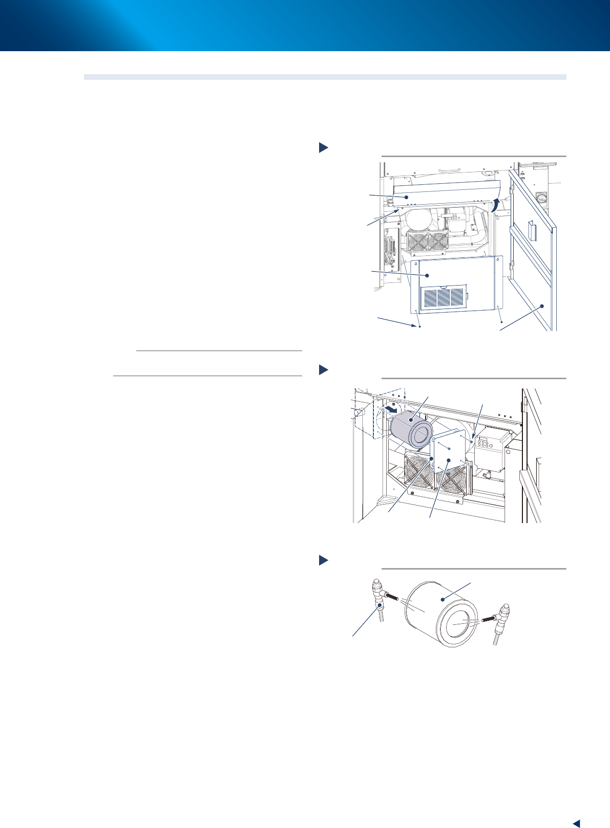
Remove the front panel.
1. Press the emergency stop button to ensure
the safety of the work.
2. Open the lower door and pull up the
maintenance door.
3. Loosen (but leave there) the upper 2 screws
on the front panel with Phillips screwdriver.
4. Pull out the lower 2 screws and remove the
front panel uplifting a little.
2
Remove 4 screws mounting the lter
cover with Phillips screwdriver and pull
out the cylindrical shape lter.
3
Clean the inside and outside of lter
with an air blow tool.
n
NOTE
Replace the filter when it is badly soiled, or cannot be
cleaned up thoroughly.
4
Insert the lter into its original position
and reattach the lter cover.
5
Reattach the front panel and put the
maintenance door and lower door back
in place.
1. Tighten the screws on the front panel with
Phillips screwdriver.
2. Pull down the maintenance door and close
the lower door.
Opening the cover
Step 1
Maintenance
door
Just loosen the
upper 2 screws.
Front panel
Screw
Lower door
53301-KMJ-00
Pulling out the filter
Step 2
Filter
Screw
Filter cover
Gasket
53302-KMJ-00
Cleaning the filter
Step 3
Filter
Air blow tool
53303-KMJ-00
2. Monthly maintenance
3-6
Chapter 3 Periodic maintenance items
2.4.2 Visual inspection of blower hose
The blower hose deteriorated and cracked cannot perform normal mask vacuum and intervenes the solder
printing. YSP10 monitors the mask vacuum pressure upon actuating the cleaning unit, using the negative
pressure gauge of cleaning unit. But, separately from that, visual inspection is recommended approximately
once a month to prevent any trouble.
1
Prepare for work.
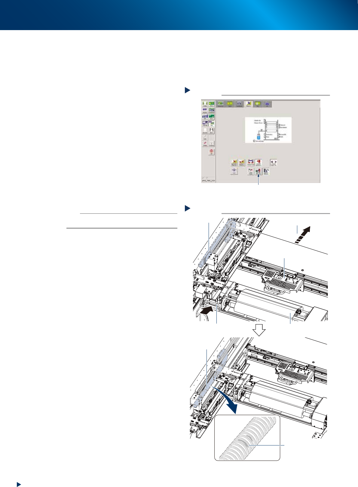
1. Press the [Cleaner Connect] button on [Unit]
- [Cleaner] screen and connect the cleaning
unit and camera unit.
e
2. Press the emergency stop button and open
machine safety cover and lower door, lift up
the maintenance door.
3. Move the squeegee unit to machine rear
side by grabbing its handle.
2
Check the blower hose condition
visually.
Check if there is any wound, crack or
deterioration and discoloring caused by
repeating motion, by grabbing the cleaning
unit handle and moving the cleaning unit and
camera unit to machine rear side.
n
NOTE
When any wound or crack on the blower hose is found,
replace it by referring Ch4 "2. Blower hose"
3
Return machine safety cover,
maintenance door and lower door to
their original position, then cancel the
emergency stop.
4
Return the cleaning unit to its original
position by pressing the [Cleaner
Connect] button on [Unit] - [Cleaner]
button again.
The cleaning unit moves to its original position
(front side of machine) and disconnects from
the camera unit.
Checking blower hose condition
Step 2
Camera unit
Cleaner
Check blower
hose condition
No crack or discoloring
on blower hose
Blower hose
Move to machine rear side
Handle
Checking blower hose condition
Step 2
Camera unit
Cleaner
Check blower
hose condition
No crack or discoloring
on blower hose
Blower hose
Move to machine rear side
Handle
533A2-KMJ-00
Connecting cleaner and camera unit
Step 1
Press the [Cleaner Connect] button.
54349-KMJ-00
2. Monthly maintenance
3-7
Chapter 3 Periodic maintenance items
2.5 CX-axis, CY-axis and cleaning unit
This section describes the procedures of cleaning and lubrication for CX-axis and CY-axis of camera unit.
Conduct same procedure for the cleaning unit at the same time because it is located on the CY-axis.
2.5.1 Cleaning and lubricating the CX-axis
The procedure to access to CX-axis varies between the standard type machine and the optional type
machine (installed "Automatic mask exchange unit" and/or "Universal mask holder").
This section describes each procedures of cleaning and lubricating CX-axis, for both "Standard type" and
"Optional type".
█
Standard type
1
Evacuate the squeegee unit by the work
from front side.
e
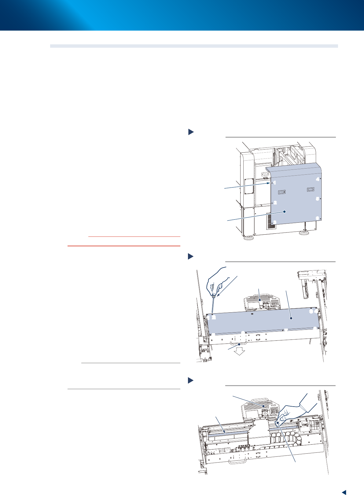
1. Press the emergency stop button and open
machine safety cover.
2. Move squeegee unit to machine front side
grabbing its handle.
2
Detach machine rear cover by the work
from rear side.
1. Loosen 6 screws on the rear cover of
machine with a Phillips screwdriver. Then
remove the cover uplifting.
c
CAUTION
Be careful not to be injured by dropping down the cover.
2. Holding the handle, evacuate the squeegee
unit to convenient position (front side) for the
work from rear side.
3
Remove the CX-axis cover by the work
from rear side.
Loosen 8 screws mounting CX-axis
cover with a Phillips screwdriver, then
remove the cover.
4
Clean the CX-axis ball screw.
1. Wipe away the grease or soiling of CX-axis
ball screw with lint-free cloth.
2. Move the camera unit to the opposite side
to clean the rest part.
n
NOTE
Wipe off carefully the lead groove area of the ball screw
and the groove area of the guide as well. Be sure that the
cloth, etc., being used to clean the ball screw does not
produce lint, etc.
Detaching machine rear cover
Standard type
Step 2
6 screws
Machine rear cover
1
2
3
4
5
6
1
2
3
4
5
6
53387-KMJ-00
Detaching CX-axis cover
Step 2,3
Phillips screwdriver
CX-axis cover
Handle
Machine rear side
Camera unit
1
2
3
4
5
6
7
8
1
2
3
4
5
6
7
8
53311-KMJ-00
Cleaning CX-axis ball screw
Step 4
Lint-free cloth
Camera unit
CX-axis ball screw
53312-KMJ-00