YSP10_Mainte_E.pdf - 第69页
3. 3-month maintenance 3-22 Chapter 3 Periodic maintenance items 5 Clean up around the W2-axis. e 1. Pres s the emerg ency stop b utton to open the safety cover and the lower door , then pul l up the maintenance door . 2…
3. 3-month maintenance
3-21
Chapter 3 Periodic maintenance items
3. 3-month maintenance
The items which should be made periodic inspection and maintenance every 3 month are shown below.
It is also recommended to shorten the maintenance interval depending on the operating time or the
environment of the machine.
3.1 W-axis
This section describes the way of cleaning and lubrication for the conveyor automatic width axes (W1-axis,
W2-axis, and W3-axis) of YSP10. W1-axis and W3-axis are of the entrance or exit, and W2-axis is of the
center conveyor.
3.1.1 Cleaning and lubrication of W-axis
1
Prepare for work.
e
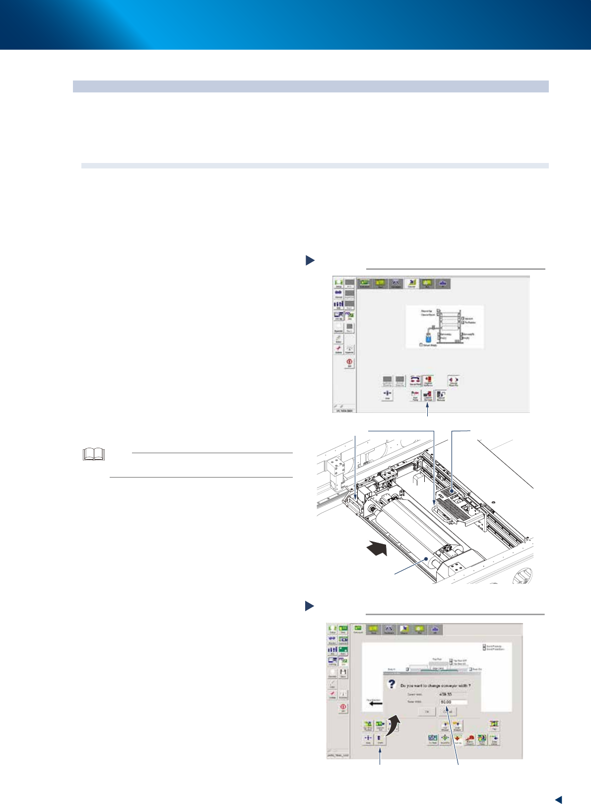
1. Press the [Cleaner Connect] button on [Unit]
- [Cleaner] screen to connect the cleaning
unit and camera unit.
2. Press the emergency stop button and open
machine safety cover and the lower door
and lift up the maintenance door.
3. Move the squeegee unit to rear side of
machine grabbing its handle.
4. Move the cleaning unit and camera unit to
rear side grabbing one of their handle.
2
Remove all the backup pins or the
board support jigs on the matrix plate.
3
Read voluntary board data.
TIP
Reading a board data makes it possible to change the
conveyor width.
4
Change the conveyor width to its
minimum width.
1. Close 3 doors which opened at Step1 to
cancel the emergency stop.
2. Press the [Width] button on the [Unit] -
[Conveyor] tab screen.
3. Input the minimum value of the conveyor
width "50mm" in the "Target width" box and
press the [OK] button.
Changing the conveyor width minimum
Step 4
Press the [Width] button Enter “50”
54305-KMJ-00
Moving cleaning unit and camera unit
Step 1
Press the [Cleaner Connect] button
Handle
Camera unit
Cleaning unit
Move to machine rear side
54304-KMJ-10
3. 3-month maintenance
3-22
Chapter 3 Periodic maintenance items
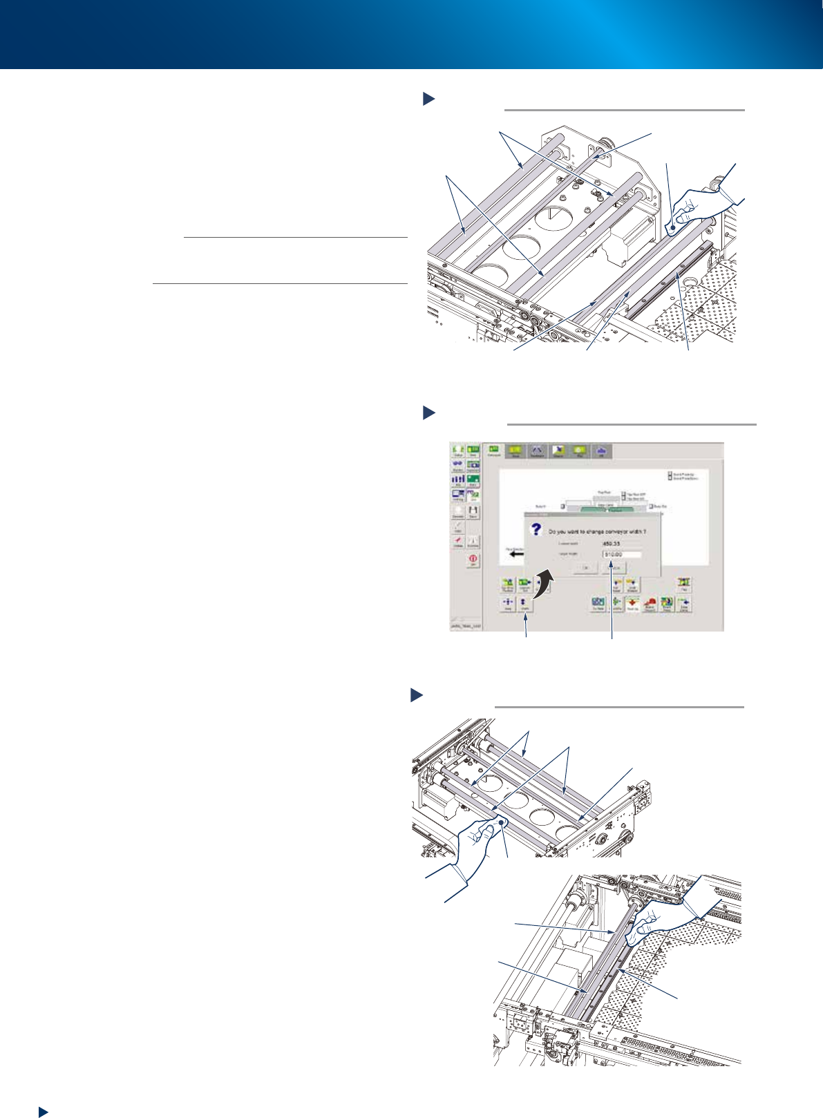
5
Clean up around the W2-axis.
e
1. Press the emergency stop button to open the
safety cover and the lower door, then pull
up the maintenance door.
2. Wipe the old grease and soiling from the
ball screws (2 positions), guides (2 positions)
and hexagon spline (1 position) with a
lint-free cloth .
n
NOTE
Carefully wipe the lead grooves and the guide grooves of
the ball screw. Additionally, make sure that any dirt is not
remained.
6
Clean up around the W1- and W3-axes.
Wipe the old grease and soiling from the ball
screws (4 positions), shaft guides (4 positions)
and hexagon splines (2 positions) with a
lint-free cloth, as same as W2-axis .
7
Change the conveyor width to its
maximum width.
1. Close 3 doors which opened at Step1 to
cancel the emergency stop.
2. Press the [Width] button on the [Unit] -
[Conveyor] tab screen.
3. Input the maximum value of the conveyor
width "510mm" in the "Target width" box
and press the [OK] button.
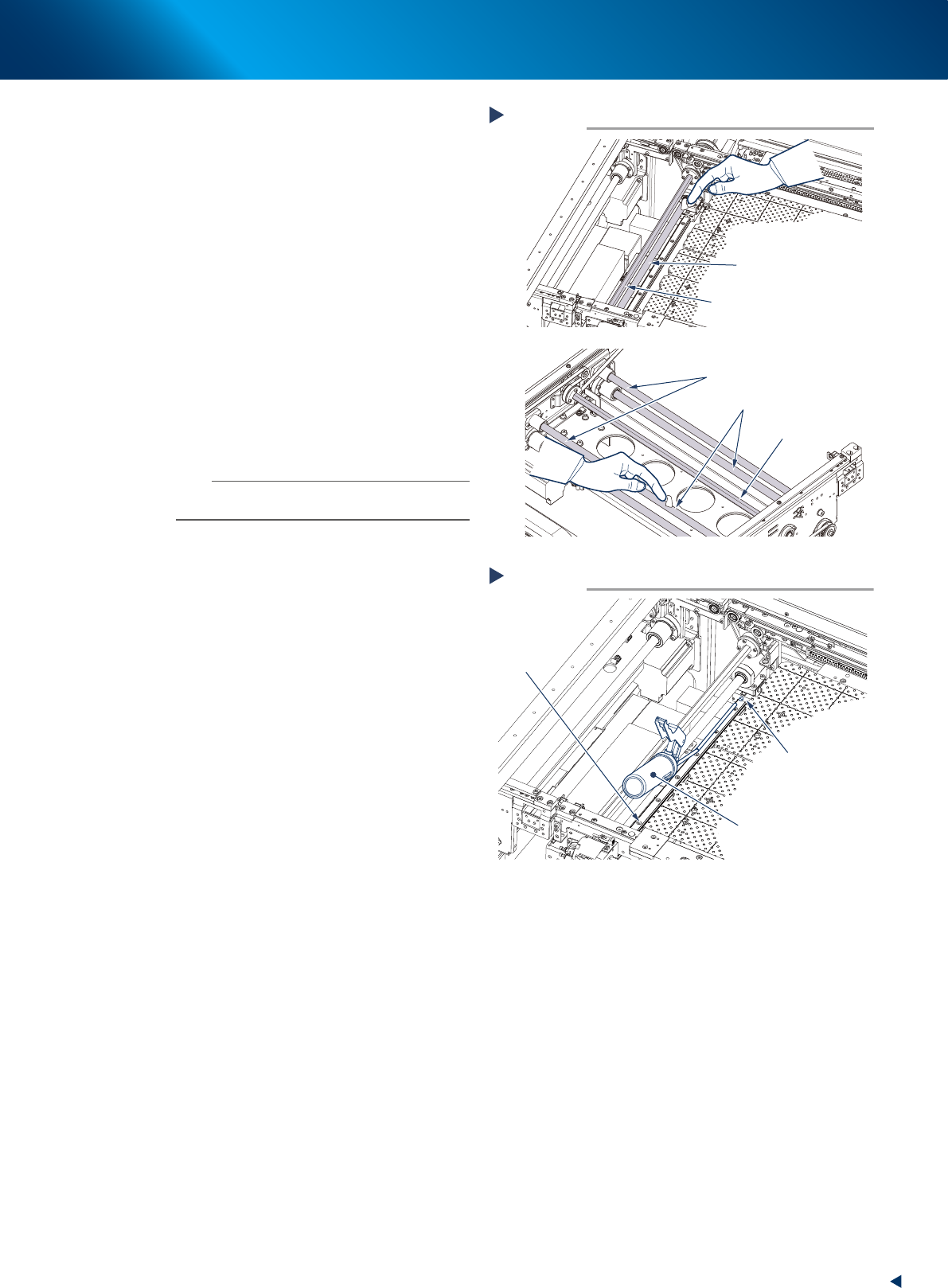
8
Clean the rest of the part.
e
1. Press the emergency stop button and open
machine safety cover, lower door and
maintenance door.
2. Wipe off the remaining grease or soiling
remained after Step5 and Step6 with
lint-free cloth.
Cleaning the W-axis (minimum conveyor width)
Step 5, 6
Lint-free cloth
Hexagon spline
Hexagon spline
W2-axis guide
W3-axis shaft guide
W2-axis ball screw
W3-axis
ball screw
53306-KMJ-00
Cleaning the W-axis (maximum conveyor width)
Step 8
Lint-free cloth
Hexagon spline
Hexagon spline
W2-axis guide
W1(3)-axis shaft guide
W1(3)-axis ball screw
W2-axis
ball screw
53307-KMJ-00
Changing the conveyor width maximum
Step 7
Press the [Width] button
Enter “510”
54308-KMJ-00
3. 3-month maintenance
3-23
Chapter 3 Periodic maintenance items
9
Apply grease to the ball screws and the
hexagon splines.
W2-axis
Apply the specified grease (NSL) by hand
uniformly over the surfaces of the ball screws (2
positions) and the hexagon spline (1 position)
and grooves.
W1- and W3-axes
Apply the specified grease (NSL) by hand
uniformly over the surfaces of the ball screws (2
positions each), the hexagon spline (1 position
each) and the shaft guides (2 position each)
and grooves.
0
Apply grease to the guide of W2-axis
with a grease gun.
Use a grease gun (bend type nozzle) to inject
the prescribed grease (NSL) at the grease
nipples (2 positions) of the guide.
n
NOTE
Inject until the grease begins to seep out from the gap
between guide block and guide.
q
Change the conveyor width to its
minimum width with the procedure of
Step4.
w
Apply grease to the rest of the ball
screws.
e
1. Press the emergency stop button to open
machine safety cover, lower door and
maintenance door.
2. Apply the specified grease (NSL) by hand
uniformly over the surfaces of the ball
screws and grooves where the grease could
not be applied in Step9.
e
Spread the grease.
1. Close maintenance door, lower door and
machine safety cover, and cancel the
emergency stop.
2. Change the conveyor width from maximum
to minimum several times with the
procedures of Step7 and 4.
r
Wipe away excess grease.
e
1. Press the emergency stop button and open
machine safety cover, lower door and
maintenance door.
2. Wipe all excess grease from the edge of
guide and ball screw with lint-free cloth.
Manual lubrication for W2-axis
Step 9
Hexagon spline
W2-axis ball screw
Hexagon spline
W1(3)-axis shaft guides
W1(3)-axis ball screws
53309-KMJ-00
Lubrication for W2-axis guide
Step 10
Grease gun
(bend type nozzle)
Grease nipple
W2-axis
guide
53310-KMJ-00