YSP10_Mainte_E.pdf - 第89页
Chapt er 4 The p ar ts t o be replace d and it s pro ce dure s Contents 1. Scraper unit 4-1 1. 1 Metal squeegee 4-1 1.2 Urethane squeegee 4-2 2. Blower hos e 4-3 3. Convey or tr ansfer belt 4-5 4. Mask v acuum unit 4- 13…
4. 6-month maintenance
3-41
Chapter 3 Periodic maintenance items
6
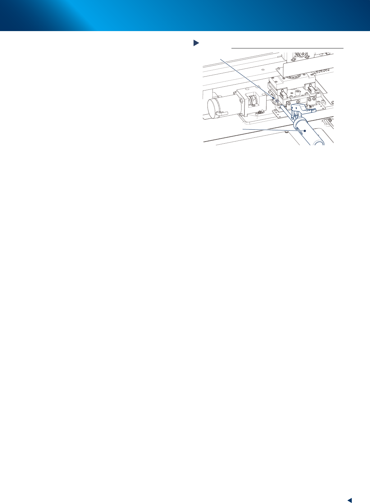
Inject the X2-axis ball screws.
1. Using a grease gun (standard type nozzle),
inject the prescribed grease (NSL) at the
grease nipples of the X2-axis ball screw,
until the grease seep out.
2. Then wipe away excess grease to clean.
7
Apply grease to X2-axis and Y direction
guides.
1. Apply the specified grease (NSL) by hand
uniformly over the surfaces of the X2-axis
guides (2 positions) and the Y direction
guides (2 positions).
2. Then apply the grease uniformly over the
surfaces of the Y-axis guides (2 positions)
and the X direction guides (2 positions).
8
Reattach machine covers to their
original position.
1. Close the lower door of machine front.
2. Return machine rear cover.
• Standard type:
Reattach machine rear cover to its original
position using Phillips screwdriver.
• With automatic mask exchange unit:
• Close upper rear cover.
• Reattach center rear cover using Phillips
screwdriver.
Lubricating X2-axis ball screw
Step 6
Grease gun
(standard type nozzle)
X2-axis grease nipple
53355-KMJ-00

1. Scraper unit
4-1
Chapter 4 The parts to be replaced and its procedures
1. Scraper unit
The squeegee of YSP10 can be replaced its scraper unit alone. When the wound, crack or wear are
found on the inspection, replace the scraper unit according to the procedure below.
1.1 Metal squeegee
The scraper unit of metal squeegee can be deformed by hitting to somewhere. In that case, the deformed
unit can be replaced by loosening the bolts mounting the scraper unit from upper surface.
1
Remove the side plate attached to both
side of the squeegee, as shown in the
illustration on the right.
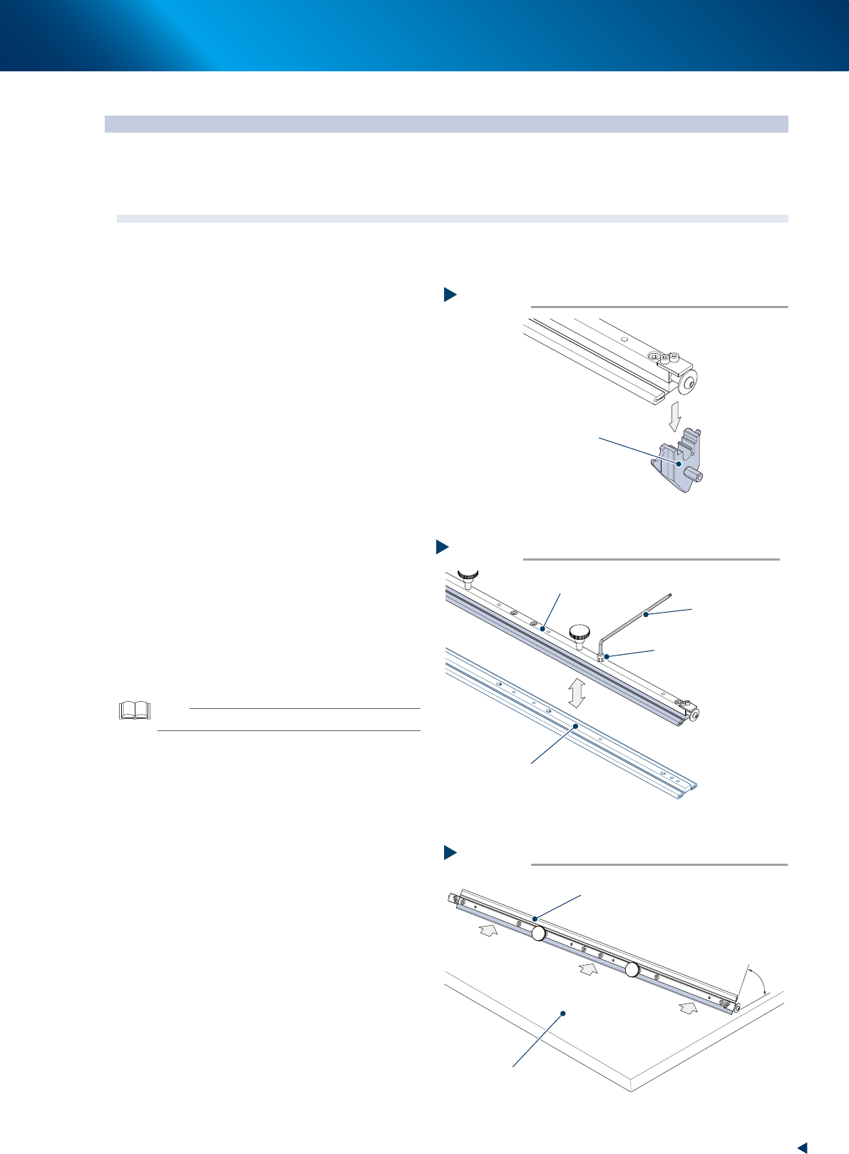
2
Remove the squeegee ame using the
4mm hex wrench to loosen the bolt
xing the scraper unit to its ame.
3
Attach the squeegee ame to the new
scraper unit using 4mm hex wrench
temporarily.
4
Check the attaching conditions as
follows:
1. Remove the protection cover for squeegee.
2. Press the squeegee blade against the surface
plate or some surface having firm flatness
with an attack angle.
3. Check that there is no gap in the position
indicated by the arrow as shown on the
right. Loosen the fixing bolts and adjust it so
that there is no gap.
4. The adjusting procedure is completed,
tighten the fixing bolts.
TIP
The default attack angle is 55 degrees.
5
Attach the side plates to the squeegee
by the reverse procedure of removing.
Remove the side plates.
Step 1
Side plate
53410-KMJ-00
Remove the squeegee flame
Step 2
Squeegee flame
Hex wrench (4mm)
Fixing bolt
New scraper unit
53411-KMJ-00
Check the squeegee attachment status.
Step 4
The surface plate or
the surface having firm flatness
Protection cover
Attack angle
53412-KMJ-00