YSP10_Mainte_E.pdf - 第93页
2. Blower hose 4-4 Chapter 4 The parts to be replaced and its procedures 5 Pull off the old blower hose as follows: 1. Remove the hos e sett lement bracke t. 2. Pull off the old blower hose. 6 Attac h the new blo wer hos…
2. Blower hose
4-3
Chapter 4 The parts to be replaced and its procedures
2. Blower hose
This section describes the replacement procedure for the blower hose.
1
Press the [Return to origin] button on
the setup screen after ensuring safety.
Then the printing table moves to
machine rear side.
2
e
Press the emergency stop button and
open machine safety cover. Ensure to
set the emergency stop status to
perform operation safely.
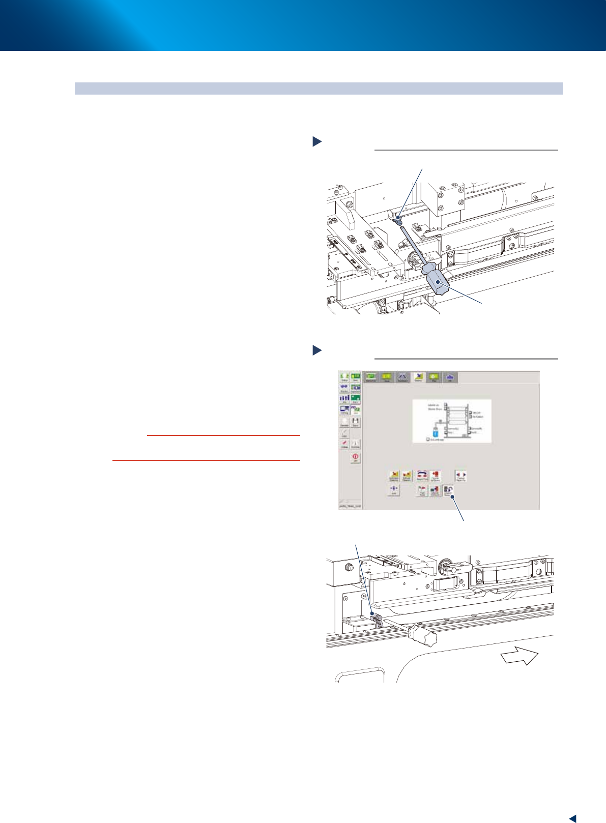
3
Loosen the hose band using the at-
head screwdriver to remove the
cleaning unit side of the blower hose
from joint.
4
Remove the pump side of the blower
hose as follows:
1. Press the [Cleaner release] button on the
[Units] - [Cleaner] tab.
2. Move the cleaner unit to the position not to
interfere the procedure.
3. Loosen the hose band as same procedure as
Step3 and remove the blower hose from
joint.
c
CAUTION
When moving the cleaning unit holding its handle, make
sure not to contact your hand to other units.
Removing cleaner side of hose
Step 3
Hose band of cleaner side
Flat-head screwdriver
53416-KMJ-00
Removing pump side of hose
Step 4
Hose band of pump side
Evacuate
the cleaning unit.
[Cleaner release] button
54400-KMJ-00
2. Blower hose
4-4
Chapter 4 The parts to be replaced and its procedures
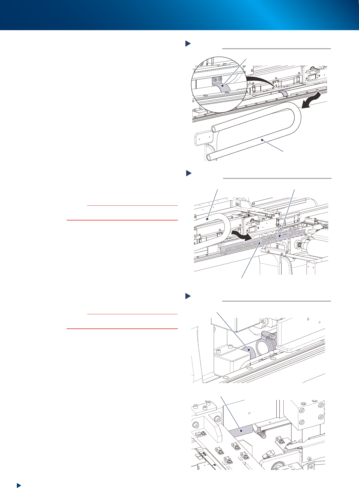
5
Pull off the old blower hose as follows:
1. Remove the hose settlement bracket.
2. Pull off the old blower hose.
6
Attach the new blower hose as follows:
1. Wipe away the dirt and old grease from the
hose guide with a lint-free cloth.
2. Apply the grease thinly with your fingers on
the hose guide.
3. Insert the new blower hose alongside of the
hose guide.
4. Attach the hose settlement bracket.
7
Connect the pump side end of the
blower hose temporarily to the joint.
8
Fix the cleaning unit end of the blower
hose as follows:
1. Move the cleaning unit to the front side by
hands.
2. Connect the blower hose to the joint and fix
the hose band with the flat-head screwdriver.
c
CAUTION
When moving the cleaning unit holding its handle, make
sure not to contact your hand to other units.
9
Fix the pump end of the blower hose
which was temporarily connected, using
the at-head screwdriver to tighten the
hose band.
0
Move the cleaning unit to former
position as follows:
1. Move the cleaner head to former position
(front side) by hands.
2. Press the [Cleaner Release] button on the
[Unit] - [Cleaner] tab to fix the cleaner unit.
c
CAUTION
When moving the cleaning unit holding its handle, make
sure not to contact your hand to other units.
Pulling off the hose
Step 5
The hose settlement bracket
(use 4mm wrench)
Blower hose
53418-KMJ-00
Attaching the blower hose
Step 6
New blower hose
Hose guide
Clean up and apply the grease thinly.
53419-KMJ-00
Attaching the blower hose
Step 8, 9
Joint (pump end)
Joint (cleaning unit end)
53420-KMJ-00
3. Conveyor transfer belt
4-5
Chapter 4 The parts to be replaced and its procedures
3. Conveyor transfer belt
The conveyor transfer belt (hereinafter referred to as belt) should be replaced when the significant
wounds, dirt or pilling is found at the periodic inspection. Follow these steps to replace the belt.
n
NOTE
The conveyor of flow direction of "R to L" is described as example in this document. The basic procedure and required
parts are also the same for "L to R" conveyor.
█
Replacement procedure
1
Change the conveyor width to a
convenient width for maintenance
work.
1. Read any board data.
2. Press the [Width] button on [Unit] -
[Conveyor] screen to display "Conveyor
Width" screen.
3. Enter a width wide enough for a hex wrench
to be inserted in the "Target Width" box and
press the [OK] button.
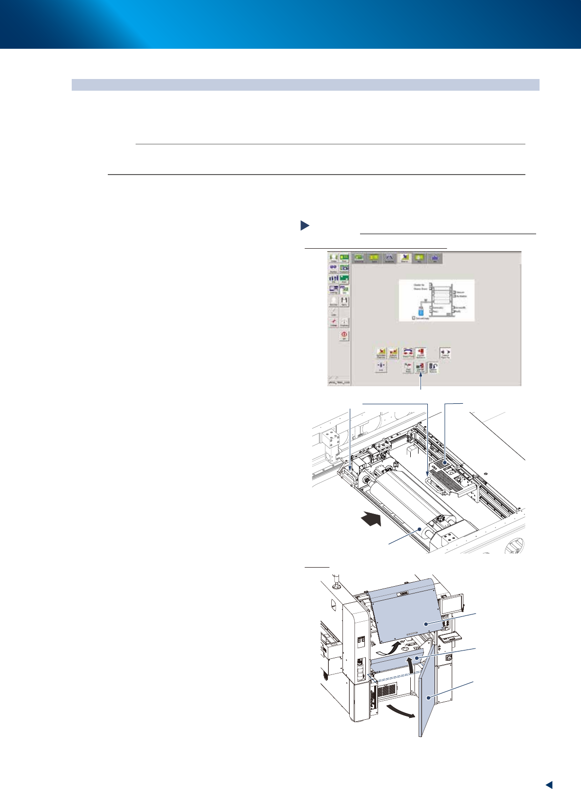
2
Prepare for work.
1. Press the [Cleaner Connect] button on [Unit]
- [Cleaner] screen to connect the cleaning
unit and camera unit.
e
2. Press the emergency stop button and open
machine safety cover.
3. Move the cleaning unit and camera unit to
machine rear side grabbing one of their
handles.
4. Open the lower door and lift up the
maintenance cover.
Preparing for work
Moving the cleaning unit and camera unit
Covers
Step 2
Press the [Cleaner Connect] button
Handle
Camera unit
Cleaning unit
Move to machine rear side
Maintenance cover
Safety cover
Lower door
54402-KMJ-00