卧式standard头部.pdf - 第14页
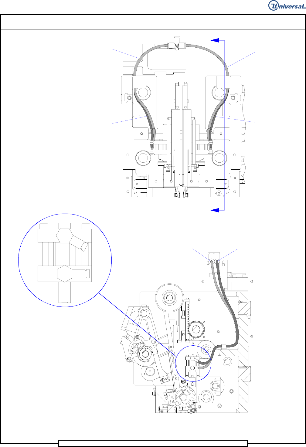
Page 12 T50090901 Rev . F V/S Standard Insertion Head Assembly This Document Supports Assembly 50090901 Rev. D Fr ont V ie w Or ient Fit tin gs a s sh ow n (bo t h side s) B B (Y el lo w Tu bi n g) (Y el lo w Tu bi n g) …

Page 13
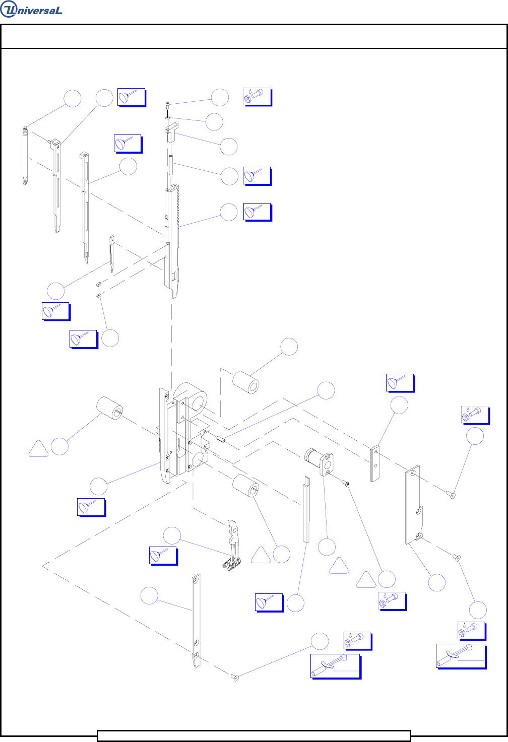
V/S Standard Insertion Head Assembly T50090901 Rev. F
This Document Supports Assembly 50090901 Rev. D
Notes
1
Torque on shaft not to exceed 10 inch ounces when fully assembled.
2
Hand tighten Knurled Collar Clamp, then tighten screw, and screws in pulley.
3
Ensure that there is no axial play in Shaft Assembly before tightening Collar Clamp.
4
Mount Duplex Bearings face to face. Align arrows as shown (< >).
5
Orient Bushings as shown.
6
Do not tighten Screws until Tooling Housing is fully assembled to Head Assy. This permits
Bushings to be correctly aligned to Lead Screw.
7
Insert the Shaft through the two Ball Bushings. Tighten the preload Set Screw until drag is
observed when sliding the Shaft back and forth axially. Loosen the Set Screw until the drag is
just eliminated. Repeat for the second Ball Bushing.
8
Clean in alcohol, spray with primer N, apply thread lock.
9
Push pin in to rear rail, then tighten screw.
10
Ends of Fiber Optic Cables to be flush with surfaces shown on Fiber Optic Bracket.
11
7.00 ± .06 Inch dimension is from edge of Sensor Assembly to the end of the Fiber Optic
Cables.
12
Locknut, Strain Relief, and washer provided with Fiber Optic Cable.
13
Used with ERV only.
14
If you are breaking fragile axial parts during centering, see IM-UPS Product Editor-New
Component.
15
The Lead Screw Bushings are coated with TFE and do not require lubrication. DO NOT GREASE
THE LEAD SCREW AND BUSHINGS.