卧式standard头部.pdf - 第32页
Page 30 T50090901 Rev . F V/S Standard Insertion Head Assembly This Document Supports Assembly 50090901 Rev. D The following message is displayed. 6. Click on Yes . This zeros all axes. The following screen is displayed …
Page 29
V/S Standard Insertion Head Assembly T50090901 Rev. F
This Document Supports Assembly 50090901 Rev. D
16. Click on the Quit, No Save button to exit out of the Set Up Critical
Axis Position screen.
17. With the tooling raised and if no additional set ups are to be performed,
exit out of the IM Diagnostics function.
End of procedure.
Head Chain to Tooling Alignment
Purpose:
To position the chain so the V slot in the carrier clips aligns exactly with the
V slot in the head tooling and the chain clips are aligned horizontally.
Special Tools:
Gauge Pin (.039 inch diameter - 40968505)
Adjustment Procedure:
1. Push the STOP push button.
2. Palm the machine down as detailed in the Operation Manual.
3. Activate the IM Diagnostics as follows. Refer to the IM-UPS and IM
Diagnostics documentation for specific details relating to the operation
of the machine terminal.
Select the IM Diagnostics icon.
WARNING
When the machine is in the IM Diagnostics function power is provided to
the machine. Exercise caution when performing the following
procedures to avoid Injury to personnel and equipment.
4. Palm the machine up and push the INTLK RESET push button.
5. After the IM Diagnostics has completed its initialization, select the fol-
lowing. Machine Set Up>Critical Axis Positions
Page 30
T50090901 Rev. F V/S Standard Insertion Head Assembly
This Document Supports Assembly 50090901 Rev. D
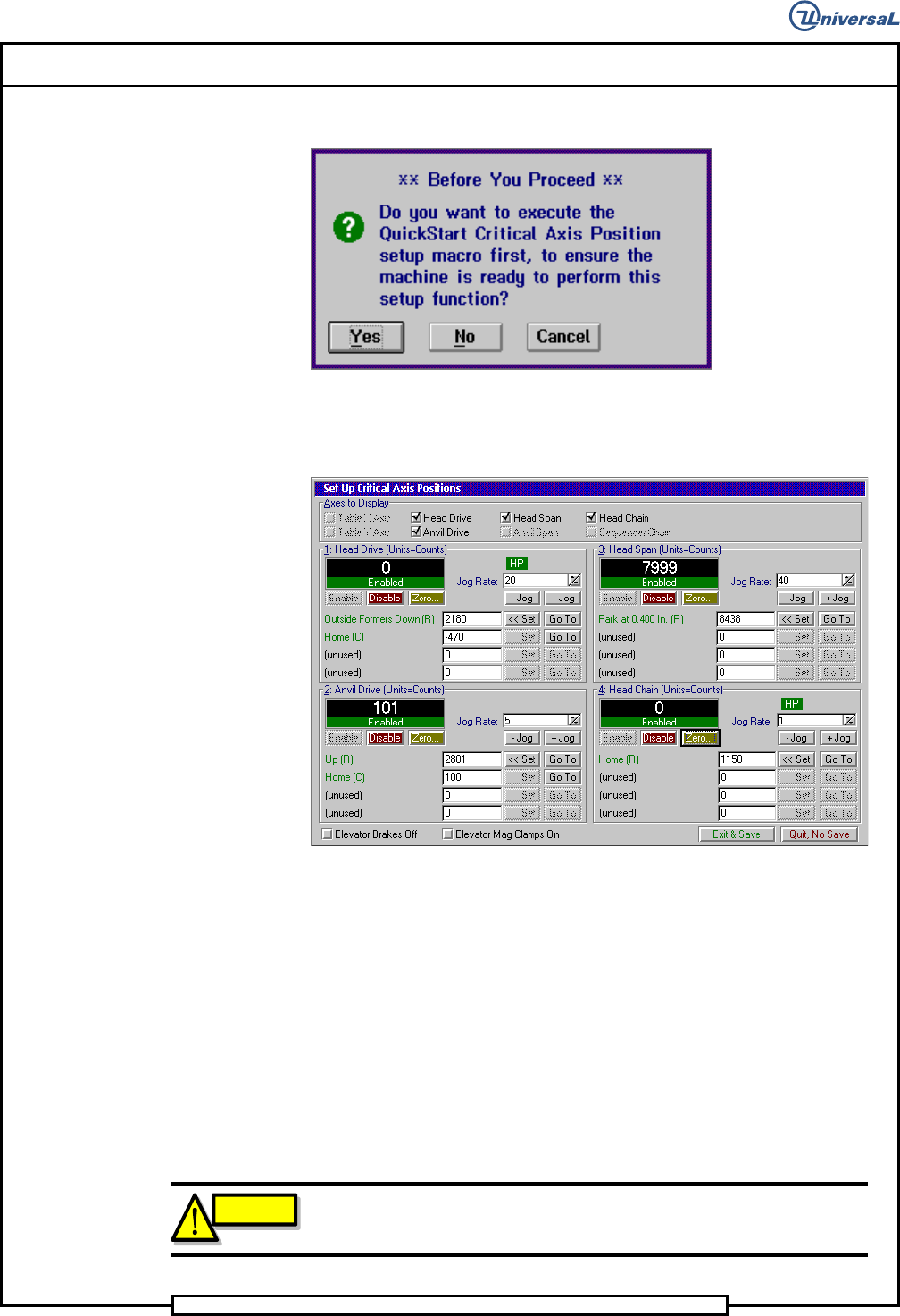
The following message is displayed.
6. Click on Yes. This zeros all axes.
The following screen is displayed
7. Because the Head Drive axis is disabled, zero the head drive axis again
then actuate the -Jog 200 counts to move the tooling out of the way.
8. Insert the gauge pin in corresponding chain clips at the repair position
in the head chains.
9. In the Set Up Critical Axis Positions screen, click on the Head Chain
then Enable to enable the chain drive.
10. With the head chain zeroed, open the BEC arm then jog the head chain
positive until the gauge pin aligns with the right hand shear blade V
groove. Jog the head tooling down to move the V groove close to the
gauge pin.
CAUTION
To prevent damage to the head tooling, ensure that the tooling is fully
retracted before moving the head chain to remove the gauge pin.
Page 31
V/S Standard Insertion Head Assembly T50090901 Rev. F
This Document Supports Assembly 50090901 Rev. D
11. Click on Set to save the setting.
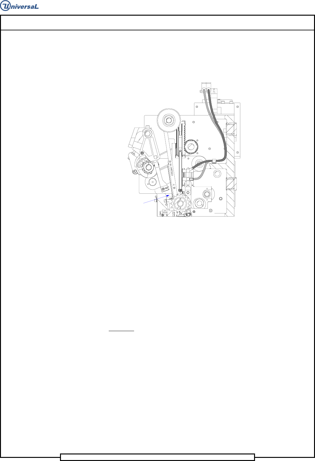
12. Loosen the three cap screws in the drive pulley then using the 7/16
wrench, turn the left hand chain shaft until the gauge pin aligns with
the V groove in the left hand tooling.
Repair Position
13. Tighten the three cap screws in the drive pulley then click on Set to
save the setting.
14. Close the BEC arm and remove the gauge pin from the head chain.
15. If no additional set ups are to be performed, exit out of the IM Diag-
nostics function.
End of procedure.
Part Missing Detector Adjustment
Purpose:
To set the detector sensitivity to properly detect missing parts.
Procedure:
1. Palm the machine down as detailed in the Operation Reference manual.
2. Refer to the sensor illustration for set up.