卧式standard头部.pdf - 第35页
Page 33 V/S Standard Insertion Head Assembly T50090901 Rev . F This Document Supports Assembly 50090901 Rev. D Indic ator: Indicates the current position of the sensitivity adjustment trimmer. One turn of the trimmer cha…
Page 32
T50090901 Rev. F V/S Standard Insertion Head Assembly
This Document Supports Assembly 50090901 Rev. D
2.1 Place the output timer selector switch to the Output timer OFF
position.
SENS
MAX
FINE
TURBO
OFF. D
ON. D
OFF
D. ON
L. ON
FS-M1
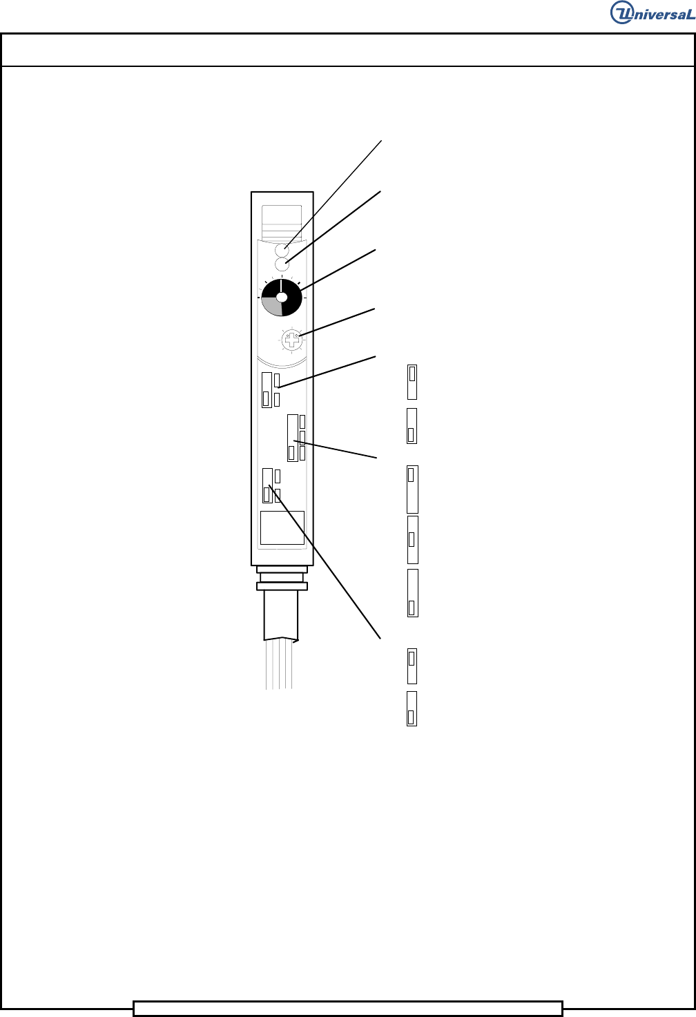
Operation indicator (Red LED):
Lights when the control output is activated.
Indicator:
Indicates the current position of the sensitivity
adjustment trimmer.
Stable operation indicator (Green LED):
Lights when a sufficient light quantity is received.
Sensitivity adjustment trimmer:
8-turn trimmer. Turning the trimmer clockwise
increases the sensitivity.
FINE/TURBO selector switch
FINE: Ultra-high accuracy
TURBO: Ultra-long detecting distance
Output timer selector switch
Output OFF-delay: 40 ms
Output ON-delay: 40 ms
Output timer OFF
.Output selector switch
DARK ON
LIGHT ON
4-conductor cable
2.2 Place the FINE/TURBO selector switch to the FINE position.
2.3 Place the Output selector switch to the LIGHT ON position.
2.4 Set the sensitivity to the minimum. (Ensure that the operation
indicator (red LED) extinguishes. If possible, keep the pointer
within the transparent window range.)

Page 33
V/S Standard Insertion Head Assembly T50090901 Rev. F
This Document Supports Assembly 50090901 Rev. D
Indicator:
Indicates the current position of the sensitivity adjustment trimmer.
One turn of the trimmer changes the pointer position by one division
on the indicator scale.
MAX
Sensitivity adjustment trimmer (8-turn):
Turning the trimmer clockwise increases the sensitivity. Turning the
trimmer counterclockwise decreases the sensitivity.
3. Refer to the illustration for sensitivity adjustment.
MIN
A
B
Optimal
position
B
A
Indicator
3.1 Turn the sensitivity adjustment trimmer clockwise. Find point A
at which the operation indicator (red LED) illuminates.
3.2 Place a .015 to .024 inch (0,38 to 0,6mm) diameter jumper wire
on the chain and move the chain so that the jumper wire is in the
path of the light beam between the transmitting and receiving
fiber optics. Note that the operation indicator (red LED)
extinguishes.
3.3 When the operation indicator (red LED) is extinguished, turn the
sensitivity adjustment trimmer clockwise to find point B at which
the operation indicator illuminates.
3.4 When the operation indicator (red LED) is illuminated, turn the
sensitivity adjustment trimmer counterclockwise to extinguish
the indicator. Then, turn the trimmer clockwise to find point B at
which the operation indicator illuminates.
3.5 Set the sensitivity to the point midway between points A and B.
NOTE
If the sensitivity difference is smaller than one division on the indicator
scale, adjust the sensitivity based on the position of the sensitivity
adjustment trimmer. If there is a difference of a least a half turn between
points A and B, stable detection is possible.
B
A
Optimal
position
3.6 Remove the jumper wire from the chain.
4. Place the Output selector switch to the DARK ON position.
End of procedure.

Page 34
T50090901 Rev. F V/S Standard Insertion Head Assembly
This Document Supports Assembly 50090901 Rev. D
Tensioning Head Chain Belts
The head chain belts are designed with built in tensioning mechanisms.
Whenever the belts are suspected of being loose due to stretching or have
been replaced, perform the following procedures to set the belt tension.
Drive Belt
Purpose:
To correctly tension the head chain drive belt.
Procedure:
1. Palm the machine down as detailed in the Operation Reference
Manual.
2. Loosen the four cap screws that secure the head drive motor to the mo-
tor mounting bracket. Loosen the screws just enough to allow the mo-
tor to move
3. Physically move the motor to ensure that the motor is pushed along the
mounting surface away from the spring.
4. Tighten the four cap screws that secure the head drive motor to the mo-
tor mounting bracket.
End of procedure.
Idler Belts
Purpose:
To correctly tension the head chain idler belts.
Procedure:
1. Palm the machine down as detailed in the Operation Reference
Manual.
2. Loosen the cap screw that secures the idler plate to the motor housing.
Loosen the screws just enough to allow the idler plate to move
3. Tighten the cap screw that secures the idler plate to the motor housing.
4. Repeat this procedure for the idler belt on the opposite side of the in-
sertion head.
End of procedure.