卧式standard头部.pdf - 第41页
Page 39 V/S Standard Insertion Head Assembly T50090901 Rev . F This Document Supports Assembly 50090901 Rev. D Adjustment Procedure: 1. Push the STOP push button. 2. Palm the machine down as detailed in the Operation Ref…
Page 38
T50090901 Rev. F V/S Standard Insertion Head Assembly
This Document Supports Assembly 50090901 Rev. D
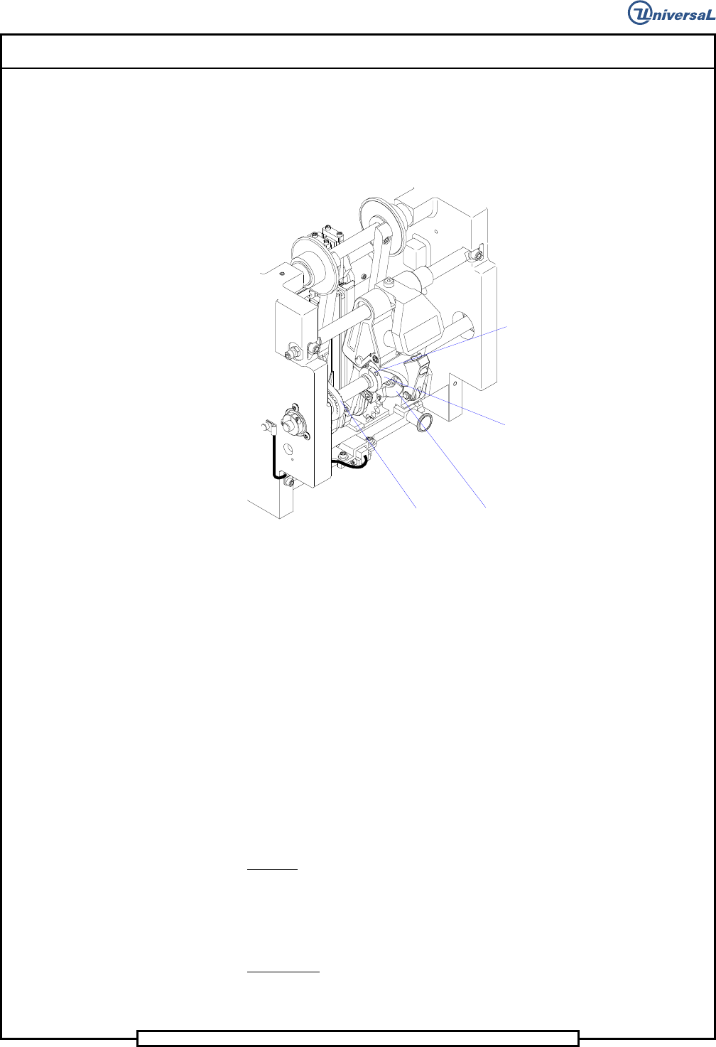
5. Rest the allen wrench on top of the cam and check if the cam is cen-
tered. If the cam is centered on the allen wrench, no adjustment is re-
quired. Centered is defined as when the sides of the allen wrench are
aligned with the sides of the cam. If the cam is not centered on the
tool, proceed as follows.
Centering Cam
Centering Drive Belt
Knurled Knob
Socket Head
Cap Screws
6. Loosen the socket head cap screw in the knurled knob next to the cam
on the side of the cam in the direction that the cam has to be adjusted.
Turn the knob away from the cam.
7. Loosen the set screw in the knurled knob on the opposite side of the
cam then turn the knurled knob until the cam is centered on the allen
wrench.
8. Turn the other knurled knob back until it contacts the cam then tighten
the set screws in both knurled knobs to secure them in position.
9. Replace the centering housing assembly.
End of procedure.
Centering Finger Alignment
Purpose:
This procedure adjusts the side to side position of the centering housing as-
sembly to ensure correct centering of components. This is the fine adjust-
ment to correct for components that are being inserted off center.
Prerequisite:
Cam Alignment
Page 39
V/S Standard Insertion Head Assembly T50090901 Rev. F
This Document Supports Assembly 50090901 Rev. D
Adjustment Procedure:
1. Push the STOP push button.
2. Palm the machine down as detailed in the Operation Reference
Manual.
3. With the 1/4 inch allen wrench between the tooling housings, manually
close the head span axis until the allen wrench is held in place.
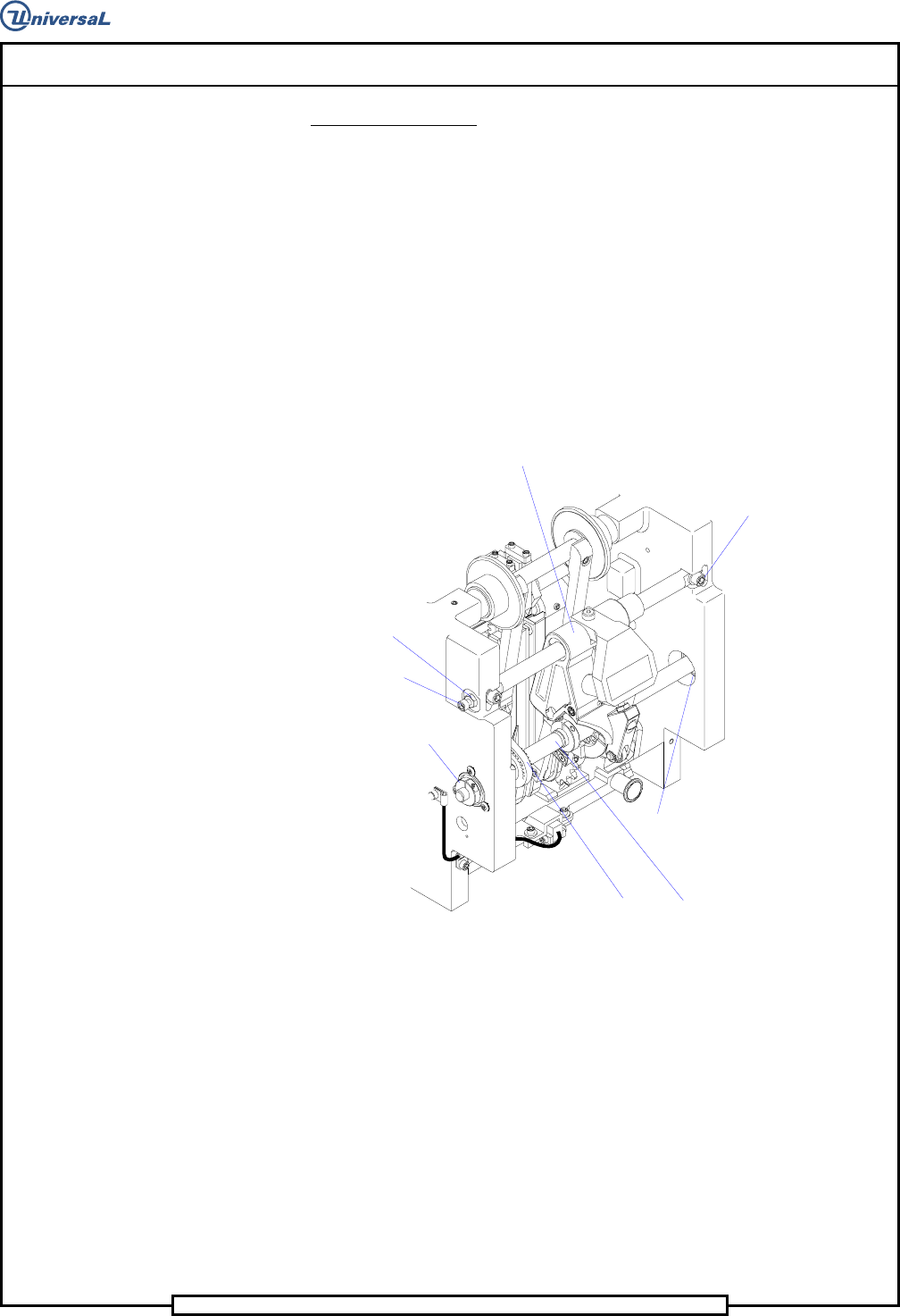
4. Loosen the hex nut at each end of the centering housing shaft then ad-
just the jacking screws so the centering fingers are centered in relation
to the tooling housings. Use the 1/4 inch allen wrench, held between
the tooling housings, as a visual guide when centering the centering
housing assembly.
Centering Cam Assembly
Centering Drive Belt
Collar Clamp
Ball Bearing
Centering Housing Assembly
Socket Head
Cap Screws
Jacking Screw
Hex Nut
5. With the centering housing assembly centered, adjust the jacking
screws against each end of the centering housing shaft. Loosen one of
the jacking screws 1/4 turn to provide a gap, .005 - .010 inch (0,1mm -
025mm), to provide easy removal and installation of the centering
housing assembly while maintaining the centering adjustment.
6. Tighten the two hex nuts to secure the jacking screws in position.
7. Manually open the tooling housings and remove the allen wrench.
End of procedure.

Page 40
T50090901 Rev. F V/S Standard Insertion Head Assembly
This Document Supports Assembly 50090901 Rev. D
Centering Finger Height Adjustment
Purpose:
This procedure adjusts the height of the centering fingers so the fingers prop-
erly engage a component at the centering position of the head chains.
Special Tools:
Gauge Pin (.039 inch diameter - 40968505)
Adjustment Procedure:
1. Push the STOP push button.
2. Palm the machine down as detailed in the Operation Reference
Manual.
3. Activate the IM Diagnostics as follows. Refer to the IM-UPS and IM
Diagnostics documentation for specific details relating to the operation
of the machine terminal.
Select the IM Diagnostics icon.
WARNING
When the machine is in the IM Diagnostics function power is provided to
the machine. Exercise caution when performing the following
procedures to avoid Injury to personnel and equipment.
4. Palm the machine up and push the INTLK RESET push button.
5. After the IM Diagnostics has completed its initialization, select the fol-
lowing. Machine Set Up>Critical Axis Positions
The following message is displayed.
6. Click on Yes. This zeros all axes.