卧式standard头部.pdf - 第53页
Page 51 V/S Standard Insertion Head Assembly T50090901 Rev . F This Document Supports Assembly 50090901 Rev. D CAUTI ON Failure to use Kluber Syntheso D32 oil as stated in our machine maintenance schedules leads to reduc…

Page 50
T50090901 Rev. F V/S Standard Insertion Head Assembly
This Document Supports Assembly 50090901 Rev. D
Ball Bushing Preload Adjustment
The following procedure describes adjustment to be made to the shaft to
bushing clearance. Slide the ball bushing shafts through the bushings. If the
shafts pass through the bushings with any grinding or binding, bushing re-
placement is necessary. When replacing the upper bushings, no preload ad-
justment is necessary. Simply press out the bushings and replace them.
Replace the lower bushings as follows.
1. Insert the shaft through the two ball bushings.
2. Tighten the preload set screw until drag is felt when sliding the shaft
back and forth.
3. Loosen the set screw until the drag is just eliminated.
4. Repeat the procedure for the second ball bushing.
Lead Screw Flanged Bushing Checks
The following procedure describes checks to be made to the lead screw
flanged bushings.
1. Thread the lead screw into the flanged bushing.
2. Clamp the housing, which supports the sleeve, so the lead screw is in a
vertical position. Hold the upper end of the lead screw shaft and pull
upwards. If any movement is detected in the vertical direction, the
sleeve must be replaced. Side to side play in this vertical position does
not indicate a bad flanged bushing.
Inside Former Check
The following procedure describes the check to be made to the inside form-
ers.
1. Remove the kick out arm assemblies from the tooling housings.
2. Clean the area between the housing and kick out arms where they pivot
then check the inside former and O-rings for wear and replace if neces-
sary.
3. Lubricate the cam surfaces and pivot hole of the kick out arm assembly
with Kluber Syntheso D32. Install the kick out arm assemblies. En-
sure that each arm is free to pivot and that the screw is tightened
against the dowel pin.

Page 51
V/S Standard Insertion Head Assembly T50090901 Rev. F
This Document Supports Assembly 50090901 Rev. D
CAUTION
Failure to use Kluber Syntheso D32 oil as stated in our machine
maintenance schedules leads to reduced tooling life and/or failure.
Syntheso D32 is a special blend specifically designed for high speed
moving and mating metal parts. No other oil is recommended.
Shear Block Check
The following procedure describes the check to be made to the shear blocks.
1. Remove the shear blocks from the kick out arm assemblies.
2. Check the shear block for wear and replace if necessary.
3. Using Loctite 222 on the threads of the screws, install the shear blocks
and secure in position with the screws.
End of procedure.
Page 52
T50090901 Rev. F V/S Standard Insertion Head Assembly
This Document Supports Assembly 50090901 Rev. D
Insertion Head Assembly
CAUTION
If the tooling housings are not centered properly damage to the head
occurs.
Special Tools:
Detent Retaining Tool (13702001)
Open End Wrench (47146101)
NOTE
When assembling the insertion head, it is recommended that the tooling
housings and centering assemblies be assembled before starting the
main insertion head assembly procedure.
Tooling Housing Assembly
CAUTION
Failure to use Kluber Syntheso D32 oil as stated in our machine
maintenance schedules leads to reduced tooling life and/or failure.
Syntheso D32 is a special blend specifically designed for high speed
moving and mating metal parts. No other oil is recommended.
Purpose:
The following details the steps required for tooling housing assembly.
Assembly Procedure:
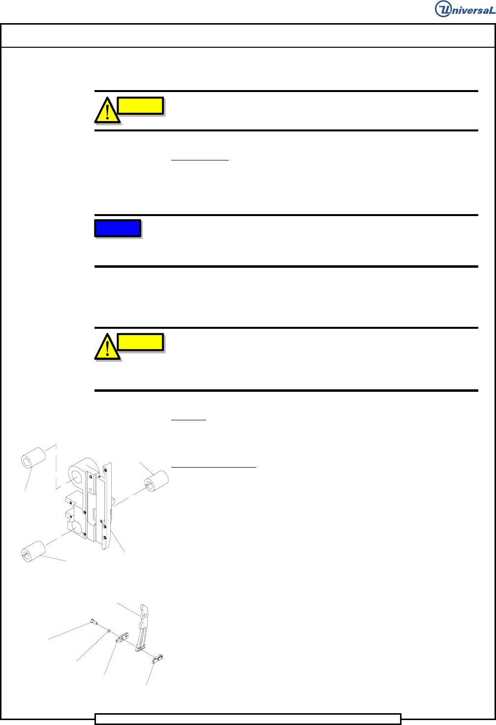
1. Install the solid ball bushing into the tooling housing so it is flush with
the outside face of the tooling housing.
Slotted Ball
Bushing
Slotted Ball
Bushing
Solid Ball
Bushing
Tooling
Housing
2. Install the two slotted ball bushings into the tooling housing with the
slots oriented as shown. Using Loctite 222 on the two 10-32 x 1/4 set
screws, secure the slotted ball bushings into the tooling housing. Insert
the shaft though the two ball bushings. Tighten the preload set screw
until drag is observed when sliding the shaft back and forth axially.
Loosen the set screw until the drag is just eliminated. Repeat for the
other tooling housing assembly.
Inside
Former
Shoulder
Screw
O-ring
Kick Out Arm
Shear
Block
3. Clean the two shoulder screws, o-rings and shear block in alcohol then
spray with primer N. Install the o-rings on the shear block, then using
Loctite 222 on the threads of the shear block, install the inside former
and shear block to the kick out arm using the shoulder screws.