卧式standard头部.pdf - 第65页
Page 63 V/S Standard Insertion Head Assembly T50090901 Rev . F This Document Supports Assembly 50090901 Rev. D Idle r Sh aft Low e r Sh aft Thr ust Wa sher s Ne ed le Bea rin g Sp acer Sp acer Thrus t Bea ring Idler Sp r…
Page 62
T50090901 Rev. F V/S Standard Insertion Head Assembly
This Document Supports Assembly 50090901 Rev. D
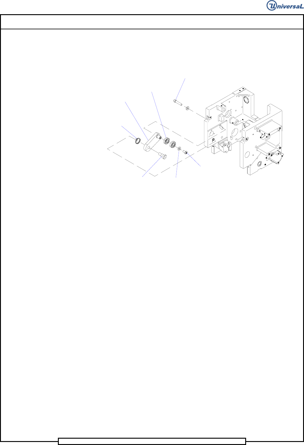
27. Install the 5/16-18 x 1 1/2 socket head cap screw through the housing
and into the tension arm. Do not tighten now, this will be used for later
adjustment.
Socket Button
Head Screw
Socket Head
Cap Screw
Thrust Washer
Radial Bearings
Shoulder Screw
T
ension
Spring
Tension Arm
28. Using Loctite 222 on the threads of four 8-32 x 1/4 socket button head
screws, install a radial bearing in each chain clip guide and secure the
bearings in the guides using the button head screws.
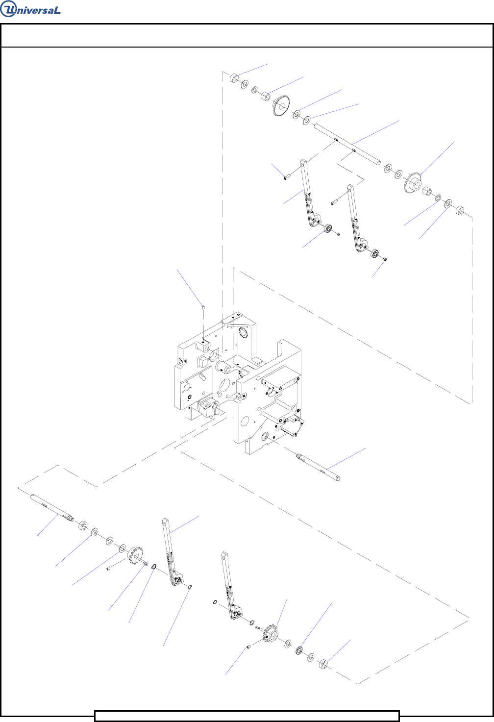
29. Slide the two lower shafts into the housing so the keyways are facing
forward. Apply a light coat of Kendall Blue Grease on the thrust bear-
ings then, on each lower shaft, install a spacer, thrust washer, thrust
bearing, thrust washer, key, sprocket, retaining ring, chain clip guide
assembly and another retaining ring.
30. Using Loctite 222 on the threads of two 1/4-20 x 5/16 set screws, se-
cure the lower sprockets to the lower shafts using the set screws.
Page 63
V/S Standard Insertion Head Assembly T50090901 Rev. F
This Document Supports Assembly 50090901 Rev. D
Idler Shaft
Lower Shaft
Thrust Washers
Needle Bearing
Spacer
Spacer
Thrust Bearing
Idler Sprocket
Socket Button
Head Screw
Radial Bearing
Socket Head
Cap Screw
Chain Clip
Guide
Set Screw
Lower Shaft
Thrust Washer
Thrust Washer
Cam Drive
Key
Retaining
Ring
Retaining
Ring
Chain Clip
Guide (Ref.)
Set Screw
Lower
Sprocket
Thrust
Bearing
Spacer
Thrust Bearings
Page 64
T50090901 Rev. F V/S Standard Insertion Head Assembly
This Document Supports Assembly 50090901 Rev. D
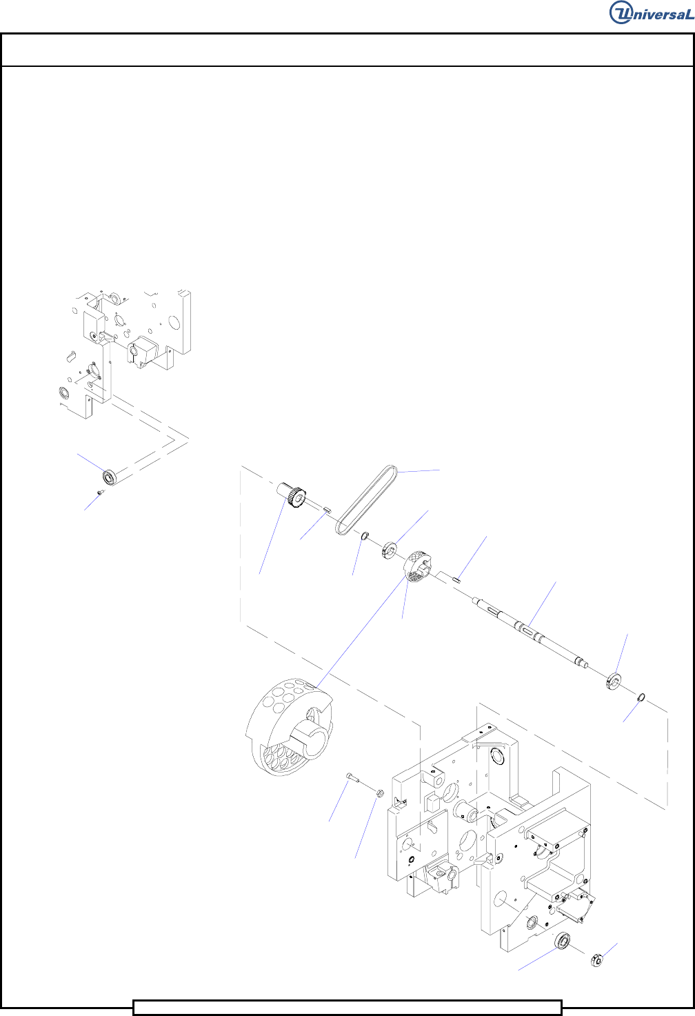
31. Install the idler shaft partially into the housing so the flat on the shaft
is facing up and the guide mounting flats are facing forward.
32. Install a spacer, thrust bearing, spacer, sprocket assembly, thrust bear-
ing, two thrust washers, thrust bearing, sprocket assembly, spacer,
thrust bearing and spacer on the idler shaft.
33. Using Loctite 222 on the threads of the two 10-32 x 5/8 socket head
cap screws, secure the chain clip guides to the idler shaft using the cap
screws.
34. Using Loctite 222 on the threads of the 10-24 x 3/8 set screw, secure
the idler shaft to the housing using the set screw.
35. Using Loctite 222 on the threads of the three 8-32 x 3/8 socket button
head screws, install the radial bearing in the left side of the housing us-
ing the button head screws.
S
ocket Button
Head Screws
Radial
Bearing
36. Install the centering cam and cam drive key on the cam shaft and se-
cure the cam to the shaft using the two collar clamps. Ensure correct
orientation of the cam as shown. Hand tighten the collar clamps
against the centering cam.
Retaining
Ring
Collar Clamp
Cam Shaft
Cam Drive Key
Centering Cam
Collar Clamp
Timing Belt (Ref.)
Retaining
Ring
Centering Driven
Pulley
Key
Hex Nut
Socket Head
Cap Screw
Collar Clamp
Radial
Bearing
Cam Orientation
Detail