卧式standard头部.pdf - 第66页
Page 64 T50090901 Rev . F V/S Standard Insertion Head Assembly This Document Supports Assembly 50090901 Rev. D 31. Install the idler shaft partially into the housing so the flat on the shaft is facing up and the guide mo…
Page 63
V/S Standard Insertion Head Assembly T50090901 Rev. F
This Document Supports Assembly 50090901 Rev. D
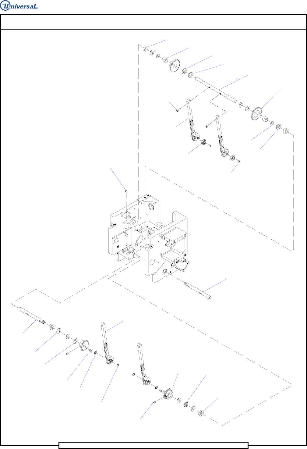
Idler Shaft
Lower Shaft
Thrust Washers
Needle Bearing
Spacer
Spacer
Thrust Bearing
Idler Sprocket
Socket Button
Head Screw
Radial Bearing
Socket Head
Cap Screw
Chain Clip
Guide
Set Screw
Lower Shaft
Thrust Washer
Thrust Washer
Cam Drive
Key
Retaining
Ring
Retaining
Ring
Chain Clip
Guide (Ref.)
Set Screw
Lower
Sprocket
Thrust
Bearing
Spacer
Thrust Bearings
Page 64
T50090901 Rev. F V/S Standard Insertion Head Assembly
This Document Supports Assembly 50090901 Rev. D
31. Install the idler shaft partially into the housing so the flat on the shaft
is facing up and the guide mounting flats are facing forward.
32. Install a spacer, thrust bearing, spacer, sprocket assembly, thrust bear-
ing, two thrust washers, thrust bearing, sprocket assembly, spacer,
thrust bearing and spacer on the idler shaft.
33. Using Loctite 222 on the threads of the two 10-32 x 5/8 socket head
cap screws, secure the chain clip guides to the idler shaft using the cap
screws.
34. Using Loctite 222 on the threads of the 10-24 x 3/8 set screw, secure
the idler shaft to the housing using the set screw.
35. Using Loctite 222 on the threads of the three 8-32 x 3/8 socket button
head screws, install the radial bearing in the left side of the housing us-
ing the button head screws.
S
ocket Button
Head Screws
Radial
Bearing
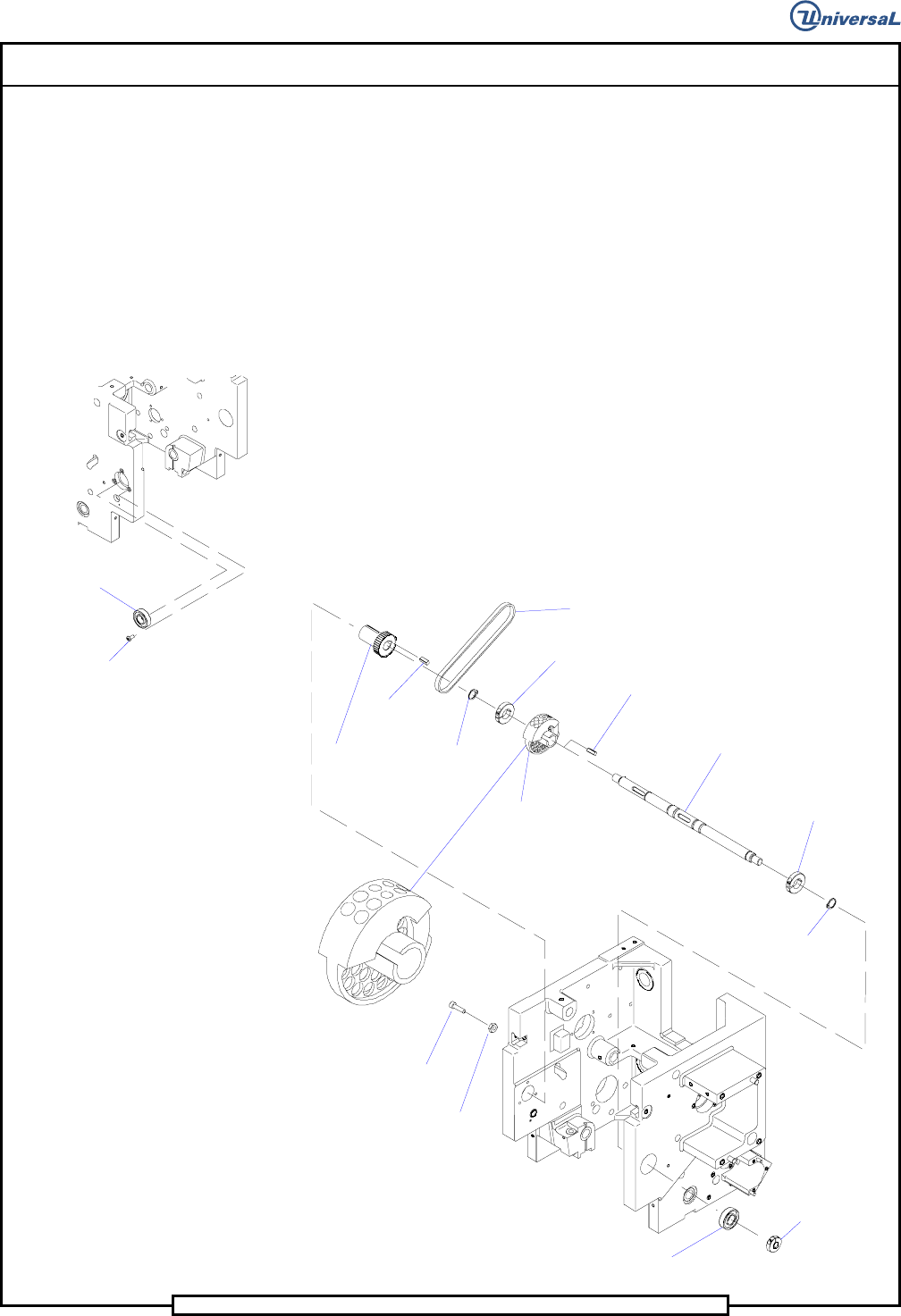
36. Install the centering cam and cam drive key on the cam shaft and se-
cure the cam to the shaft using the two collar clamps. Ensure correct
orientation of the cam as shown. Hand tighten the collar clamps
against the centering cam.
Retaining
Ring
Collar Clamp
Cam Shaft
Cam Drive Key
Centering Cam
Collar Clamp
Timing Belt (Ref.)
Retaining
Ring
Centering Driven
Pulley
Key
Hex Nut
Socket Head
Cap Screw
Collar Clamp
Radial
Bearing
Cam Orientation
Detail

Page 65
V/S Standard Insertion Head Assembly T50090901 Rev. F
This Document Supports Assembly 50090901 Rev. D
37. Install the cam shaft assembly through the right side of the housing
then install the centering driven pulley, key and retaining ring to the
left end of the cam shaft.
38. Install the retaining ring on the right end of the cam shaft.
39. Engage the timing belt on the driven pulley, then slide the cam shaft
into the radial bearing in the left side of the housing.
40. Install a radial bearing onto the right end of the cam shaft and into the
right side of the housing.
41. Install the two collar clamps on the ends of the cam shaft. Hand
tighten the collar clamps against the radial bearings then.
42. Adjust the centering driver pulley so it is aligned with the centering
driven pulley and secure the driver pulley in position using the cap
screws.
43. Install the two hex nuts on the two 10-32 x 5/8 socket head cap screws
then install one set in each side of the housing.
44. Spread the centering fingers then install the previously assembled cen-
tering assembly into the housing so the centering fingers engage either
side of the centering cam.
45. Using Loctite 222 on the threads of the two 1/4-20 x 3/4 socket head
cap screws, secure the centering assembly to the housing using the cap
screws and lock washers.
46. Using Loctite 242 on the threads of the 1/4-28 x 1 1/2 button head
screw, install a gear belt pulley into the right idler plate. Secure the
pulley to the plate using the hex jam nut, lock washer and flat washer.
47. Using Loctite 242 on the threads of the 1/4-20 x 1 socket head cap
screw, install the right idler plate assembly to the housing using a split
lock washer and flat washer.
48. Install the 1/4-20 x 2 socket head cap screw, lock washer and flat
washer through the idler plate into the housing. Do not tighten now,
this will be used for later adjustment.
49. Using Loctite 222 on the threads of the two 10-24 x 1 1/2 socket head
cap screws, install the compression spring and spring holder to the
housing using the cap screws.
50. Install the thrust washer, thrust bearing, thrust washer, drive cam key,
and gear belt pulley to the lower shaft. Ensure that there is no axial
play in the shaft assembly before tightening the collar clamp. Secure
the parts on the lower shaft using the screw in the collar clamp.