卧式standard头部.pdf - 第71页
Page 69 V/S Standard Insertion Head Assembly T50090901 Rev . F This Document Supports Assembly 50090901 Rev. D 65. Apply loctite 222 to 4 10-32 x 1 socket head cap screws. Install the motor to the motor mounting bracket …
Page 68
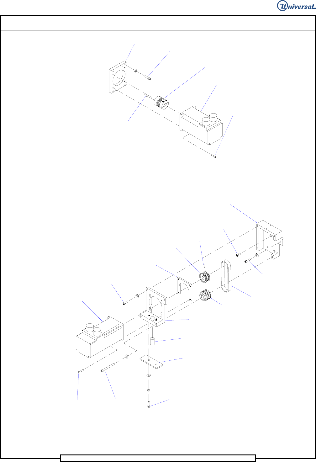
T50090901 Rev. F V/S Standard Insertion Head Assembly
This Document Supports Assembly 50090901 Rev. D
Head Drive
Motor
Socket Head
Cap Screw
Socket Head
Cap Screw
Motor Plate
Coupling (Ref.)
.190 Key (Ref.)
63. Using Loctite 242 on the threads of the three 1/4-20 x 7/8 and the 1/4-
20 x 5/8 socket head cap screws, install the motor mount bracket to the
housing using the cap screws and lock washers.
Head Chain
Drive Motor
Socket Head
Cap Screw
Socket Head
Cap Screw
Socket Head
Cap ScrewSocket Head
Cap Screw
Spring Plate
Nut Plate
Motor Mounting
Bracket
Compression Spring
Set Screw
Gear Belt
Pulley
Socket Head
Cap Screw
Socket Head
Cap Screw
Gearbelt
Pulley (Ref.)
Timing Bely
Motor Mount
Bracket
64. Using Loctite 222 on the threads of the 8-32 x 3/16 set screw, install
the gear belt pulley on the motor shaft then secure the pulley to the mo-
tor shaft using the set screw.
Page 69
V/S Standard Insertion Head Assembly T50090901 Rev. F
This Document Supports Assembly 50090901 Rev. D
65. Apply loctite 222 to 4 10-32 x 1 socket head cap screws. Install the
motor to the motor mounting bracket and nut plate using the cap
screws. Do not tighten at this time, the screws will be tightened after a
later adjustment.
66. Install the timing belt on the motor pulley then install the motor as-
sembly to the motor mounting bracket using the two 1/4-20 x 7/8 and
two 1/4-20 x 2 1/2 socket head cap screws. Engage the other end of
the timing belt on the gear belt pulley.
67. Slide the compression spring through the bottom of the motor mount-
ing bracket and secure the spring plate to the motor mounting bracket
using the two 1/4-20 x 1 socket head cap screws, compressing the
spring while tightening the screws.
68. Set the automatic belt tensioning assemblies as follows.
- Loosen the 1/4-20 x 2 socket head cap screws in the idler plates,
allow the spring to tension the belt then tighten the cap screws.
- Loosen the four 10-32 x 1 socket head cap screws in the chain
drive motor, allow the spring to tension the motor then tighten
the cap screws.
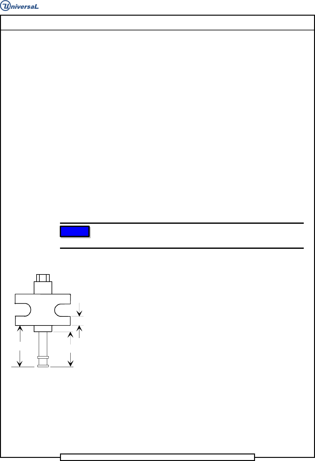
NOTE
Because the adjusting block is not symmetrical, the 0.38 inch flange
must be located at the bottom, as shown.
69. Apply Magnalube to the outer threads of the jack screw. Using Loctite
242 on the threads of the jack, install the jack, adjustment block and
jack screw to the rear flange of the housing. Adjust the height of the
adjusting block to 1.928 inch and the height of the jack screw to 1.63
inch, as shown.
1.63"
1.928"
0.38" ref.
70. Using Loctite 222 on the threads of the two 10-24 x 1/2 socket button
head screws, install the head counter bracket to the housing using the
cap screws. Install the counter to the head counter bracket using the
two 6-32 x 1/4 socket flat head screws.
71. Install the two chain clip guides to the housing using the four 10-24 x
3/8 socket head cap screws. Do not tighten the screws, as these will be
removed for head chain installation.
72. Using Loctite 222 on the threads of the four 6-32 x 1/4 socket head cap
screws, install the two light source blocks to the luminator assembly
using the cap screws.
73. Using Loctite 222 on the threads of the two 6-32 x 3/8 socket head cap
screws, install the luminator assembly to the BEC bracket using the cap
screws and flat washers.
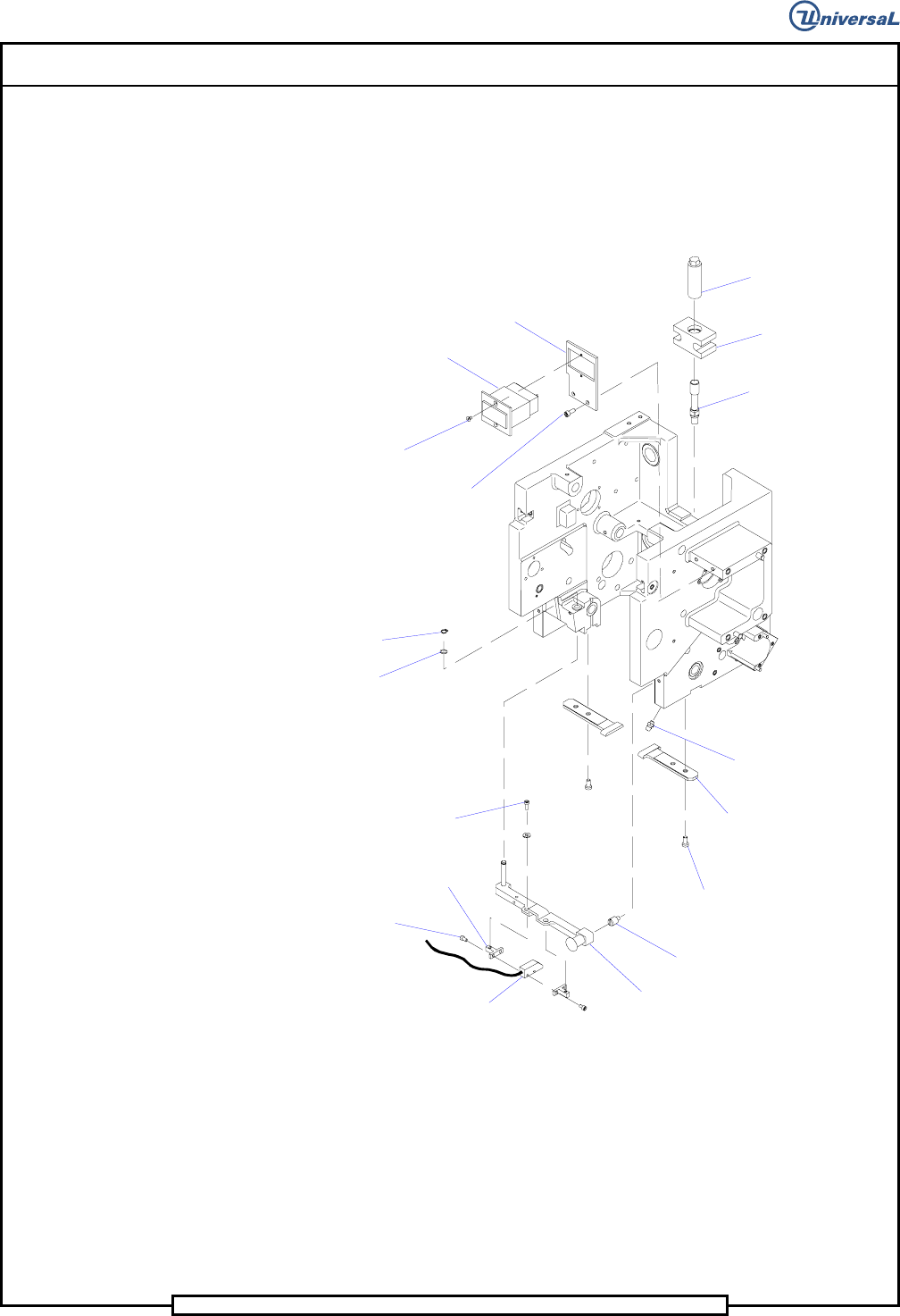
Page 70
T50090901 Rev. F V/S Standard Insertion Head Assembly
This Document Supports Assembly 50090901 Rev. D
74. Apply Magnalube to the pin of the BEC bracket assembly then install
the BEC bracket assembly into the housing and secure it in position us-
ing the spring washer and the retaining ring.
75. Using Loctite 222 on the threads of the locator pin, install the locator
pin in the housing.
Retaining
Ring
Spring
Washer
Socket Head
Cap Screw
Socket Button
Head Screw
Socket Head
Cap Screw
Socket Flat
Head Screw
Socket Head
Cap Screw
Light Source
Block
BEC Bracket
Luminator
Assembly
Locator Pin
Chain Clip
Guide
Grease Fitting
Jack Screw
Adjusting
Block
Jack
Impulse
Counter
Head Counter
Bracket
76. Install the grease fittings into the housing. Using the grease gun with
Ultra blue grease, apply the grease to the grease fittings until a slight
amount of grease is seen at the spacers.
77. Install the required icor clamps to the housing using 8-32 x 3/8 socket
head cap screws with loctite 222. All systems require 3 3/16 inch
clamps on the left side of the housing, and systems equipped with an
expanded range verifier require 3 additional clamps on the right side of
the housing. Refer to the assembly drawings section in the front of this
document for locations.