5TROUBLESHOOTING_.pdf - 第101页
3.3 . 1 Reset Procedure from Component Recognition Error ( 1 L 14 — ) Order of Error Codes ( Display C ) • ( Display A ) - ( Display B ) _ ( Cause ) • ( Remedy ) ( Display C ) 1 L 145101 ( Display A ) Number of Leads Err…
3.3
.
1
Reset
Procedure
from
Component
Recognition
Error
(
1
L
12
—
)
Order
of
Error
Codes
(
Display
C
)
_
(
Display
A
)
_
(
Display
B
)
•
(
Cause
)
•
(
Remedy
)
(
Display
C
)
1
L
123001
-
009
(
Display
A
)
Lead
Pitch
Error
(
Display
B
)
PITCH
OF
DEteCTED
LEADS
EXCEEDS
THE
TOLERANCE
1
L
12
•
…
(
Display
A
)
Lead
Pitch
Error
(
Display
B
)
PITCH
OF
LEAD
(
UPPER
)
WAS
INCORRECT
.
(
Display
C
)
1
L
125102
(
Display
C
)
1
L
125202
(
Display
A
)
Lead
Pitch
Error
(
Display
B
)
PITCH
OF
LEAD
(
LEFT
)
WAS
INCORRECT
.
(
Display
C
)
1
L
125302
(
Display
A
)
Lead
Pitch
Error
(
Display
B
)
PITCH
OF
LEAD
(
LOWER
)
WAS
INCORRECT
.
(
Display
C
)
1
L
125402
(
Display
A
)
Lead
Pitch
Error
(
Display
B
)
PITCH
OF
LEAD
(
RIGHT
)
WAS
INCORRECT
.
(
Display
B
)
PITCH
OF
ELECTRICAL
CONTACTS
1
AND
2
EXCEEDS
THE
TOLERANCE
.
:
(
Display
C
)
1112
H
110
119
(
Display
A
)
Lead
Pitch
Error
(
Display
B
)
PITCH
OF
ELECTRICAL
CONTACTS
1
AND
3
EXCEEDS
THE
TOLERANCE
.
(
Display
C
)
1112
H
210
219
(
Display
A
)
Lead
Pitch
Error
(
Cause
1
)
Wrong
parameters
(
lead
(
electrical
contact
)
pitch
)
are
set
for
the
selected
component
.
(
Remedy
1
)
Check
the
selected
component
and
the
parameters
set
in
the
"
PITCH
"
text
box
of
the
label
"
LEAD
(
ELECTC
.
)
DATA
"
in
the
component
library
data
.
If
wrong
parameters
are
set
in
the
component
library
data
,
correct
them
.
1
L
13
••
•
•
(
Display
C
)
1
L
13
B
100
199
(
Display
A
)
Lead
Horizontal
Bend
Error
(
Display
B
)
HORIZONTAL
BEND
OF
LEAD
(
UPPER
)
EXCEEDS
THE
TOLERANCE
.
(
Display
C
)
1
L
13
B
200
299
(
Display
A
)
Lead
Horizontal
Bend
Error
(
Display
B
)
HORIZONTAL
BEND
OF
LEAD
(
LEFT
)
EXCEEDS
THE
TOLERANCE
.
(
Display
C
)
1
L
13
B
300
399
(
Display
A
)
Lead
Horizontal
Bend
Error
(
Display
B
)
HORIZONTAL
BEND
OF
LEAD
(
LOWER
)
EXCEEDS
THE
TOLERANCE
.
(
Display
C
)
1
L
13
B
400
499
(
Display
A
)
Lead
Horizontal
Bend
Error
(
Display
B
)
HORIZONTAL
BEND
OF
LEAD
(
RIGHT
)
EXCEEDS
THE
TOLERANCE
.
Notes
:
(
a
)
When
the
front
-
lighting
system
is
used
to
recognize
square
and
deform
components
,
the
word
"
LEAD
”
is
changed
to
"
ELECTRICAL
CONTACT
"
.
(
b
)
The
second
digit
from
the
last
one
of
the
error
code
presents
Electrical
Contact
1
,
2
,
or
3
.
The
last
two
digits
of
IC
represent
the
lead
No
.
(
Cause
1
)
A
wrong
paramter
(
horizontal
bend
tolerance
)
is
set
for
the
selected
component
.
(
Remedy
1
)
Check
the
selected
component
and
the
parameter
set
in
the
"
HORIZONTAL
BEND
TOL
.
"
text
box
in
the
component
library
data
.
If
a
wrong
parameter
is
set
in
the
component
library
data
,
correct
it
.
3
-
9
9910
-
001
ACP
01
EERW
3
-
9
3.3
.
1
Reset
Procedure
from
Component
Recognition
Error
(
1
L
14
—
)
Order
of
Error
Codes
(
Display
C
)
•
(
Display
A
)
-
(
Display
B
)
_
(
Cause
)
•
(
Remedy
)
(
Display
C
)
1
L
145101
(
Display
A
)
Number
of
Leads
Error
1
L
14
•
•
•
•
(
Display
B
)
NUMBER
OF
THE
RANGE
LEADS
(
I
OF
SETT
(
UPPER
)
EXCEEDS
ING
.
(
Display
C
)
1
L
145201
(
Display
A
)
Number
of
Leads
Error
(
Display
B
)
NUMBER
OF
LEADS
(
LEFT
)
EXCEEDS
THE
RANGE
OF
SETTING
.
(
Display
C
)
1
L
145301
(
Display
A
)
Number
of
Leads
Error
(
Display
B
)
NUMBER
OF
LEADS
(
LOWER
)
EXCEEDS
THE
RANGE
OF
SETTING
.
(
Display
C
)
1
L
145401
(
Display
A
)
Number
of
Leads
(
Display
B
)
NUMBER
OF
LEADS
(
RIGHT
)
EXCEEDS
THE
RANGE
OF
SETTING
.
Error
(
Cause
1
)
Wrong
parameters
(
number
of
leads
)
are
set
for
the
selected
component
.
(
Remedy
1
)
Check
the
selected
boxes
of
the
label
1
If
wrong
parameters
are
set
in
the
component
library
data
,
correct
them
.
nent
and
the
paramters
set
in
the
"
1
”
,
"
2
"
,
”
3
"
,
and
"
4
"
text
l
compoi
"
NUMB
ER
OF
LEADS
”
in
the
component
library
data
.
(
Display
C
)
1
L
30
B
001
(
Display
A
)
Picked
Posture
Error
(
Display
B
)
ERROR
OF
PICK
-
UP
ANGLE
WAS
MORE
THAN
ACCEPTABLE
.
1
L
30
•
…
(
Display
C
)
1
L
30
B
002
(
Display
A
)
Picked
Posture
Error
(
Display
B
)
ERROR
OF
PICK
-
UP
X
POSITION
WAS
MORE
THAN
ACCEPTABLE
.
(
Display
C
)
1
L
33
B
003
(
Display
A
)
Picked
Posture
Error
(
Display
B
)
ERROR
OF
PICK
-
UP
Y
POSITION
WAS
MORE
THAN
ACCEPTABLE
.
(
Cause
1
)
When
a
component
is
picked
up
,
the
pick
-
up
positions
(
X
and
Y
)
and
angle
have
shifted
greatly
from
the
correct
ones
.
(
Cause
2
)
When
the
tape
is
fed
,
a
component
is
turned
vertically
.
(
Remedy
1
)
Check
the
selected
component
and
the
tape
feeder
.
Check
if
the
feeder
(
B
)
offset
data
is
correct
.
Check
if
the
component
library
data
is
correct
.
(
Remedy
2
)
Check
the
selected
component
and
the
tape
feeder
.
(
Display
C
)
1
L
31
B
001
(
Display
A
)
Center
of
Gravity
Detection
Error
(
Display
B
)
RECOGNITION
ABORTED
BECAUSE
OF
IMPROPER
COMPONENT
HANDLING
.
1
L
31
•
…
(
Cause
1
)
An
improper
vacuum
nozzle
is
selected
for
the
component
or
vice
versa
.
(
Cause
2
)
The
component
is
bent
due
to
weak
vacuum
suction
force
.
(
Remedy
1
)
Check
the
selected
component
and
vacuum
nozzle
.
(
Remedy
2
)
Check
the
vacuum
pressure
.
3
-
10
9910
-
001
ACP
01
EERW
3
-
10
3.3
.
1
Reset
Procedure
from
Component
Recognition
Error
(
1
L
32
—
)
Order
of
Error
Codes
(
Display
C
)
_
(
Display
A
)
_
(
Display
B
)
■
(
Cause
)
.
(
Remedy
)
(
Display
C
)
1
L
32
B
001
(
Display
A
)
Angle
Detection
Error
1
L
32
•
…
(
Display
B
)
RECOGNITION
ABORTED
BECAUSE
OF
IMPROPER
COMPONENT
HANDLING
.
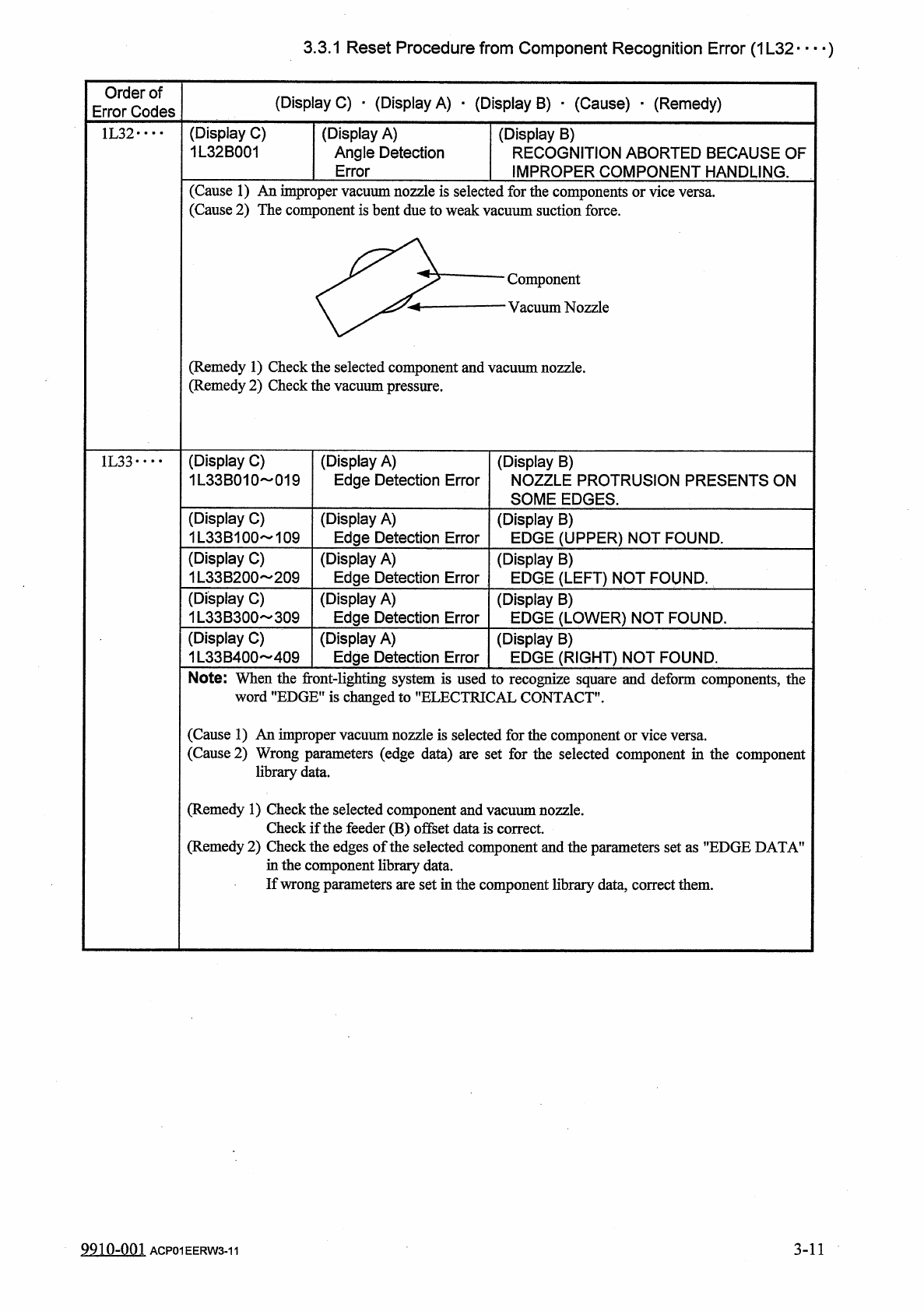
(
Cause
1
)
An
improper
vacuum
nozzle
is
selected
(
Cause
2
)
The
component
is
bent
due
to
weak
vac
forth
uums
e
components
or
vice
versa
.
;
uction
force
.
Component
Vacuum
Nozzle
(
Remedy
1
)
Check
the
selected
component
and
vacuum
nozzle
.
(
Remedy
2
)
Check
the
vacuum
pressure
.
(
Display
C
)
1
L
33
B
010
019
(
Display
A
)
Edge
Detection
Error
1
L
33
•
•
•
•
(
Display
B
)
NOZZLE
PROTRUSION
PRESENTS
ON
SOME
EDGES
.
(
Display
C
)
1
L
33
B
100
109
(
Display
A
)
Edge
Detection
Error
(
Display
B
)
EDGE
(
UPPER
)
NOT
FOUND
.
(
Display
C
)
1
L
33
B
200
~
209
(
Display
A
)
Edge
Detection
Error
(
Display
B
)
EDGE
(
LEFT
)
NOT
FOUND
.
(
Display
C
)
1
L
33
B
300
309
(
Display
A
)
Edge
Detection
Error
(
Display
B
)
EDGE
(
LOWER
)
NOT
FOUND
.
(
Display
C
)
1
L
33
B
400
409
(
Display
A
)
Edge
Detection
Error
(
Display
B
)
EDGE
(
RIGHT
)
NOT
FOUND
.
Note
:
When
the
front
-
lighting
system
is
used
to
recognize
square
and
deform
components
,
the
word
"
EDGE
"
is
changed
to
"
ELECTRICAL
CONTACT
"
.
(
Cause
1
)
An
improper
vacuum
nozzle
is
selected
for
the
component
or
vice
versa
.
(
Cause
2
)
l
parameters
(
edge
data
)
are
set
for
the
selected
component
in
the
component
data
.
(
Remedy
1
)
Check
the
selected
component
and
vacuum
nozzle
.
Check
if
the
feeder
(
B
)
offset
data
is
correct
(
Remedy
2
)
Check
the
edges
of
the
selected
component
and
the
parameters
set
as
"
EDGE
DATA
’
in
the
component
library
data
.
If
wrong
parameters
are
set
in
the
component
library
data
,
correct
them
.
9910
-
001
ACP
01
EERW
3
-
11
3
-
11