5TROUBLESHOOTING_.pdf - 第139页
Ghupteor 4 Page 4.1 Classification of Failure Symptoms and Helpful Hints on Countermeasures against Failure 4.1 . 1 Classification of Failure Symptoms … . 4.1 . 2 Helpful Hints on Countermeasures against Failure 4.2 Trou…
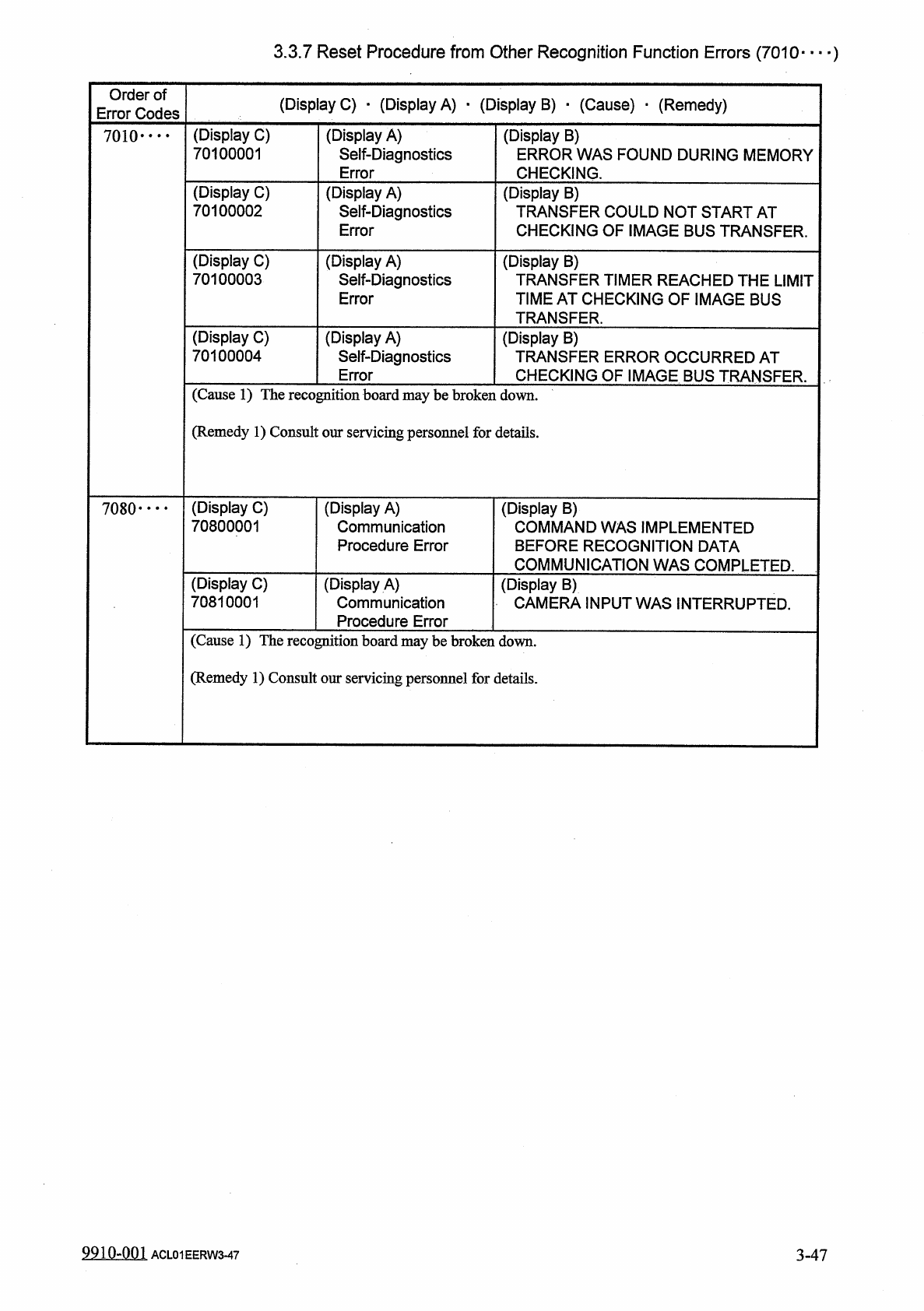
3.3
.
7
Reset
Procedure
from
Other
Recognition
Function
Errors
(
7010
—
)
Order
of
Error
Codes
(
Display
C
)
•
(
Display
A
)
•
(
Display
B
)
_
(
Cause
)
•
(
Remedy
)
(
Display
A
)
Self
-
Diagnostics
Error
(
Display
C
)
70100001
(
Display
B
)
ERROR
WAS
FOUND
DURING
MEMORY
CHECKING
.
7010
•
…
(
Display
C
)
70100002
(
Display
B
)
TRANSFER
COULD
NOT
START
AT
CHECKING
OF
IMAGE
BUS
TRANSFER
.
(
Display
A
)
Self
-
Diagnostics
Error
(
Display
C
)
70100003
(
Display
A
)
Self
-
Diagnostics
Error
(
Display
B
)
TRANSFER
TIMER
REACHED
THE
LIMIT
TIME
AT
CHECKING
OF
IMAGE
BUS
TRANSFER
.
(
Display
C
)
70100004
(
Display
A
)
Self
-
Diagnostics
Error
(
Display
B
)
TRANSFER
ERROR
OCCURRED
AT
CHECKING
OF
IMAGE
BUS
TRANSFER
.
(
Cause
1
)
The
recognition
board
maybe
broken
down
.
(
Remedy
1
)
Consult
our
servicing
personnel
for
details
.
(
Display
C
)
70800001
(
Display
A
)
Communication
Procedure
Error
(
Display
B
)
COMMAND
WAS
IMPLEMENTED
BEFORE
RECOGNITION
DATA
COMMUNICATION
WAS
COMPLETED
.
7080
•
…
(
Display
C
)
70810001
(
Display
A
)
Communication
Procedure
Error
(
Display
B
)
CAMERA
INPUT
WAS
INTERRUPTED
.
(
Cause
1
)
The
recognition
board
maybe
broken
down
.
(
Remedy
1
)
Consult
our
servicing
personnel
for
details
.
99104
)
01
3
-
47
ACL
01
EERW
3
-
47
Ghupteor
4
Page
4.1
Classification
of
Failure
Symptoms
and
Helpful
Hints
on
Countermeasures
against
Failure
4.1
.
1
Classification
of
Failure
Symptoms
…
.
4.1
.
2
Helpful
Hints
on
Countermeasures
against
Failure
4.2
Troubleshooting
on
Pick
-
Up
Errors
4.2
.
1
Cause
and
Remedy
of
Pick
-
Up
Errors
4.2
.
1.1
Component
-
Based
Factors
4.2
.
1.2
Machine
-
Based
Factors
4.2
.
2
Symptom
-
Based
Troubleshooting
4.2
.
2.1
Frequent
Failures
on
Specific
Vacuum
Nozzle
4.2
.
2.2
Frequent
Failures
on
Specific
Feeder
Slot
No
.
(
Lane
)
4
-
1
4
-
1
4
-
2
4
-
3
4
-
3
4
-
3
4
-
4
4
-
5
4
-
5
4
-
6
4.2
.
3
Trouble
Cases
4.2
.
3.1
Failure
(
Component
Remaining
in
Square
Cavity
of
Tape
)
4.2
.
3.2
Component
Recognition
Error
(
Lead
Detection
Error
)
4.2
.
3.3
Component
Recognition
Error
(
Corner
Detection
Error
)
4.3
Troubleshooting
for
Placement
Errors
4.3
.
1
Cause
and
Remedy
of
Placement
Errors
4.3
.
1.1
Positional
and
Angular
Deviations
of
Component
Placement
4.3
.
1.2
Missing
Components
on
P
.
C
.
B
.
4.3
.
2
Symptom
-
Based
Troubleshooting
4.3
.
2.1
Component
Placement
Marks
at
Specified
Positions
on
P
.
C
.
B
.
Lands
4.3
.
2.2
No
Component
Placement
Marks
at
Specified
Positions
on
P
.
C
.
B
.
Lands
.
…
4
-
16
4
-
8
4
-
9
4
-
10
4
-
11
4
-
11
4
-
11
4
-
13
4
-
15
4
-
15
nnna
-
nn
.
s
ACP
01
EERCC
4
-
1
Page
4.3
.
2.3
Positional
and
Angular
Deviations
of
Component
Placement
4
-
17
4
-
18
4.3
.
3
Trouble
Cases
4.3
.
3.1
Generation
of
Angular
Deviation
(
Approx
.
10
°
)
during
Component
Placement
4.3
.
3.2
Generation
of
Angular
Deviation
(
Approx
.
90
°
)
during
Component
PJacement
4.3
.
3.3
Generation
of
Missing
Component
(
Component
Carried
Away
)
by
Specific
Head
4
-
18
4
-
19
4
-
20
0
-
001
ACP
01
EERCC
4
-
2