5TROUBLESHOOTING_.pdf - 第140页
Page 4.3 . 2.3 Positional and Angular Deviations of Component Placement 4 - 17 4 - 18 4.3 . 3 Trouble Cases 4.3 . 3.1 Generation of Angular Deviation ( Approx . 10 ° ) during Component Placement 4.3 . 3.2 Generation of A…
Ghupteor
4
Page
4.1
Classification
of
Failure
Symptoms
and
Helpful
Hints
on
Countermeasures
against
Failure
4.1
.
1
Classification
of
Failure
Symptoms
…
.
4.1
.
2
Helpful
Hints
on
Countermeasures
against
Failure
4.2
Troubleshooting
on
Pick
-
Up
Errors
4.2
.
1
Cause
and
Remedy
of
Pick
-
Up
Errors
4.2
.
1.1
Component
-
Based
Factors
4.2
.
1.2
Machine
-
Based
Factors
4.2
.
2
Symptom
-
Based
Troubleshooting
4.2
.
2.1
Frequent
Failures
on
Specific
Vacuum
Nozzle
4.2
.
2.2
Frequent
Failures
on
Specific
Feeder
Slot
No
.
(
Lane
)
4
-
1
4
-
1
4
-
2
4
-
3
4
-
3
4
-
3
4
-
4
4
-
5
4
-
5
4
-
6
4.2
.
3
Trouble
Cases
4.2
.
3.1
Failure
(
Component
Remaining
in
Square
Cavity
of
Tape
)
4.2
.
3.2
Component
Recognition
Error
(
Lead
Detection
Error
)
4.2
.
3.3
Component
Recognition
Error
(
Corner
Detection
Error
)
4.3
Troubleshooting
for
Placement
Errors
4.3
.
1
Cause
and
Remedy
of
Placement
Errors
4.3
.
1.1
Positional
and
Angular
Deviations
of
Component
Placement
4.3
.
1.2
Missing
Components
on
P
.
C
.
B
.
4.3
.
2
Symptom
-
Based
Troubleshooting
4.3
.
2.1
Component
Placement
Marks
at
Specified
Positions
on
P
.
C
.
B
.
Lands
4.3
.
2.2
No
Component
Placement
Marks
at
Specified
Positions
on
P
.
C
.
B
.
Lands
.
…
4
-
16
4
-
8
4
-
9
4
-
10
4
-
11
4
-
11
4
-
11
4
-
13
4
-
15
4
-
15
nnna
-
nn
.
s
ACP
01
EERCC
4
-
1
Page
4.3
.
2.3
Positional
and
Angular
Deviations
of
Component
Placement
4
-
17
4
-
18
4.3
.
3
Trouble
Cases
4.3
.
3.1
Generation
of
Angular
Deviation
(
Approx
.
10
°
)
during
Component
Placement
4.3
.
3.2
Generation
of
Angular
Deviation
(
Approx
.
90
°
)
during
Component
PJacement
4.3
.
3.3
Generation
of
Missing
Component
(
Component
Carried
Away
)
by
Specific
Head
4
-
18
4
-
19
4
-
20
0
-
001
ACP
01
EERCC
4
-
2
4.1
Classification
of
Failure
Symptoms
and
Helpful
Hints
on
Countermeasures
against
Failure
4.1
Classification
of
Failure
Symptoms
and
Helpful
Hints
on
Countermeasures
against
Failure
4.1
.
1
Classification
of
Failure
Symptoms
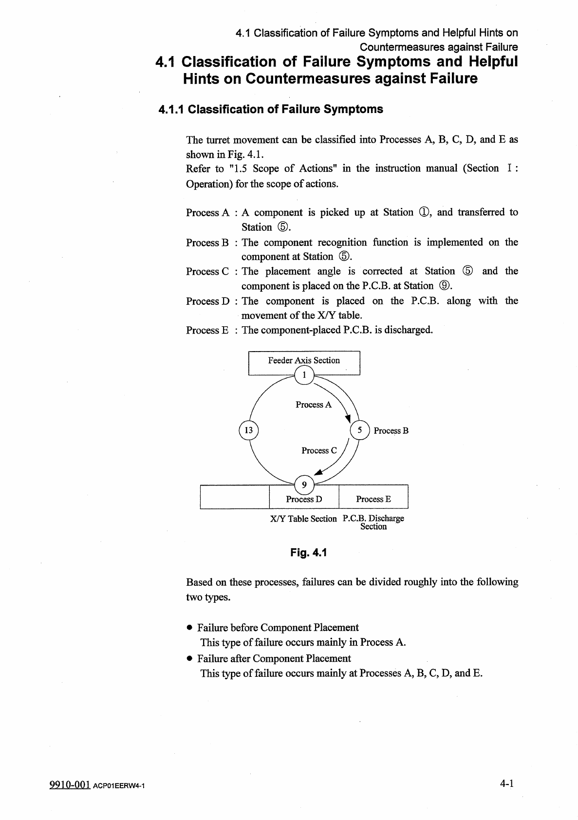
The
turret
movement
can
be
classified
into
Processes
A
,
B
,
C
,
D
?
and
E
as
Refer
to
"
1.5
Scope
of
Actions
"
in
the
instruction
manual
(
Section
I
:
Operation
)
for
the
scope
of
actions
.
Process
A
:
A
component
is
picked
up
at
Station
®
5
and
transferred
to
Station
⑤
.
Process
B
:
The
component
recognition
function
is
implemented
on
the
component
at
Station
⑤
.
Process
C
:
The
placement
angle
is
corrected
at
Station
(
5
)
and
the
component
is
placed
on
the
P
.
C
.
B
.
at
Station
⑨
.
Process
D
:
The
component
is
placed
on
the
P
.
C
.
B
.
along
with
the
movement
of
the
X
/
Y
table
.
Process
E
:
The
component
-
placed
P
.
C
.
B
.
is
discharged
.
P
.
C
.
B
.
Discharge
Section
X
/
Y
Table
Section
Fig
.
4
,
1
Based
on
these
processes
,
failures
can
be
divided
roughly
into
the
following
two
types
.
•
Failure
before
Component
Placement
This
type
of
failure
occurs
mainly
in
Process
A
.
•
Failure
after
Component
Placement
This
type
of
failure
occurs
mainly
at
Processes
A
,
B
,
C
,
D
,
and
E
.
4
-
1
9910
-
001
ACP
01
EERW
4
-
1