5TROUBLESHOOTING_.pdf - 第149页
4.2 Troubleshooting on Pick - Up Errors 4.2 . 3.2 Component Recognition Error ( Lead Detection Error ) 1 . Applicable Components S - MINI Diode 2 . Contents of Deficiency Component recognition errors ( lead detection err…
4.2
Troubleshooting
on
Pick
-
Up
Errors
4.2
.
3
Trouble
Cases
4.2
.
3.1
Failure
(
Component
Remaining
in
Square
Cavity
of
Tape
)
1
.
Applicable
Components
2125
C
(
t
=
0.8
mm
)
2
.
Contents
of
Deficiency
Pick
-
up
errors
have
occurred
by
2
to
3
%
because
some
components
have
remained
in
the
square
cavities
of
the
Components
fall
frei
tape
once
they
are
set
in
the
tape
feeder
.
e
tape
.
ely
when
they
are
not
set
in
the
tape
feeder
but
they
stick
to
the
bottom
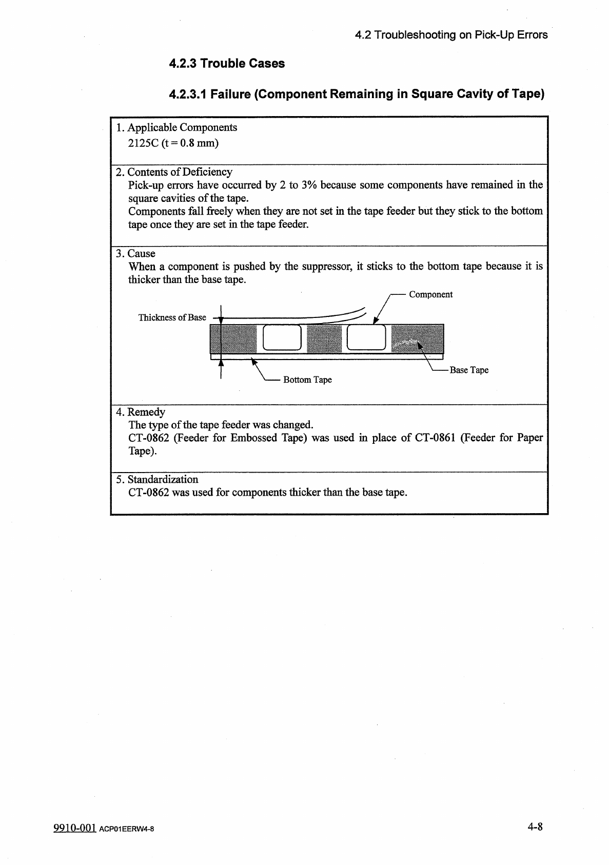
3
.
Cause
When
a
component
is
pushed
by
the
suppressor
,
it
sticks
to
the
bottom
tape
because
it
is
thicker
than
the
base
tape
.
Thickness
of
Base
Base
Tape
Bottom
Tape
4
.
Remedy
The
type
of
the
tape
feeder
was
changed
.
CT
-
0862
(
Feeder
for
Embossed
Tape
)
was
used
in
place
of
CT
-
0861
(
Feeder
for
Paper
Tape
)
.
5
.
Standardization
CT
-
0862
was
used
for
components
thicker
than
the
base
tape
.
4
-
8
9910
-
001
ACP
01
EERW
4
-
8
4.2
Troubleshooting
on
Pick
-
Up
Errors
4.2
.
3.2
Component
Recognition
Error
(
Lead
Detection
Error
)
1
.
Applicable
Components
S
-
MINI
Diode
2
.
Contents
of
Deficiency
Component
recognition
errors
(
lead
detection
errors
)
occurred
by
0.3
%
3
.
Cause
TH
"
text
box
of
the
label
"
LEAD
DATA
"
in
the
component
m
the
actual
lead
dimension
.
was
specified
for
both
"
LEAD
1
"
and
"
LEAD
2
"
in
the
dimensional
drawing
of
the
component
maker
.
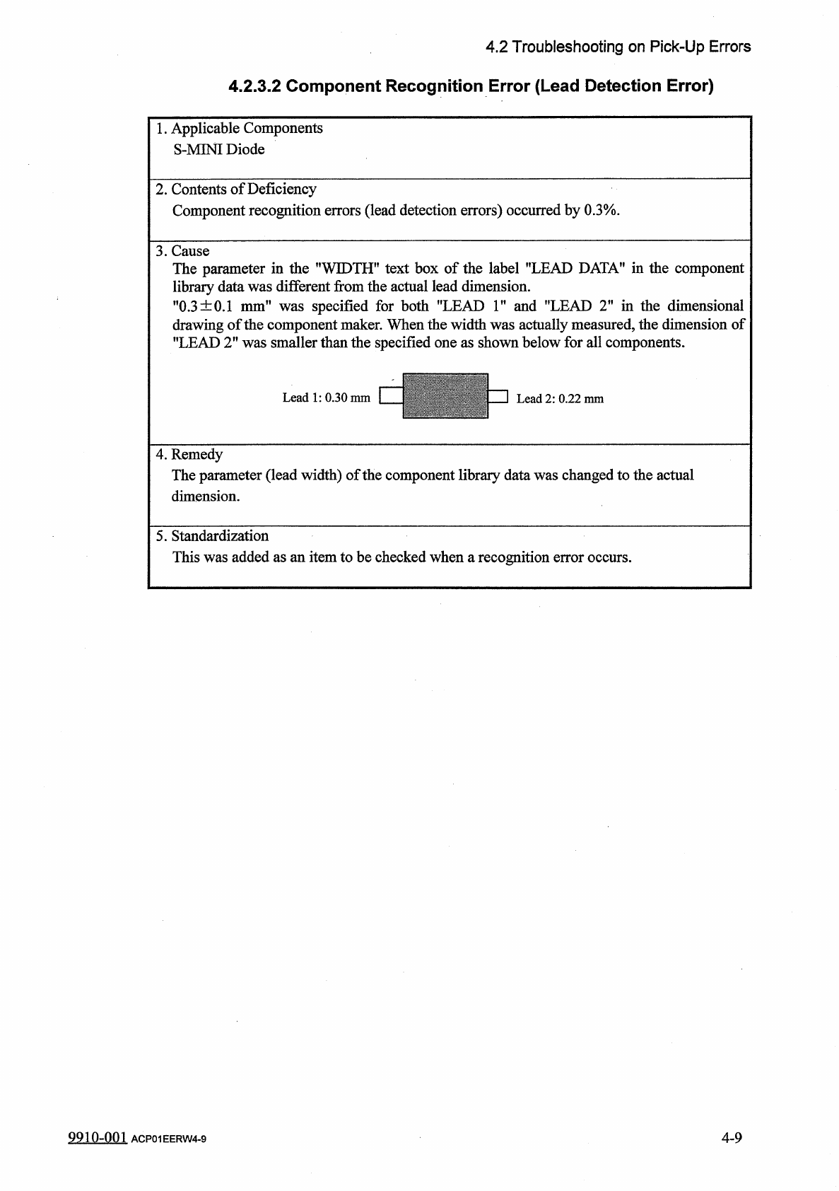
When
the
width
was
actually
measured
,
the
dimension
of
"
LEAD
2
"
was
smaller
than
the
specified
one
as
shown
below
for
all
components
.
The
parameter
in
the
T
library
data
was
differe
:
"
0.3
±
0.1
mm
"
,
WID
nt
fro
:
4
.
Remedy
The
parameter
(
lead
width
)
of
the
component
library
data
was
changed
to
the
actual
dimension
.
5
.
Standardization
This
was
added
as
an
item
to
be
checked
when
a
recognition
error
occurs
.
9910
-
001
ACP
01
EERW
4
-
9
4
-
9
4.2
Troubleshooting
on
Pick
-
Up
Errors
4.2
.
3.3
Component
Recognition
Error
(
Corner
Detection
Error
)
1
•
Applicable
Components
1005
X
2
-
Arrayed
Resistance
Network
2
.
Contents
of
Deficiency
Component
recognition
errors
(
comer
detection
errors
)
occurred
by
0.3
%
.
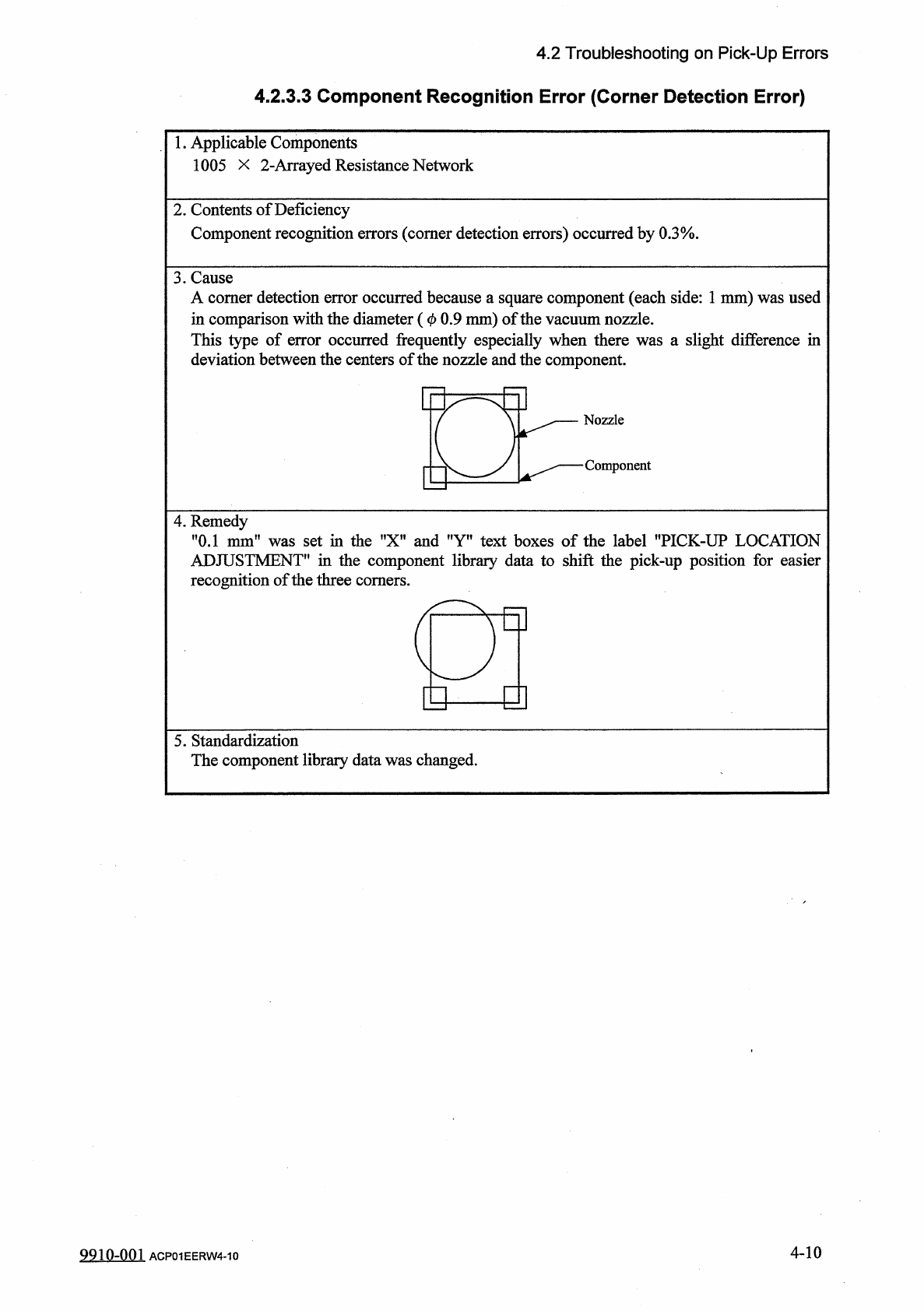
3
.
Cause
A
comer
detection
error
occurred
because
a
square
component
(
each
side
:
1
mm
)
was
used
in
comparison
with
the
diameter
(
0
0.9
mm
)
of
the
vacuum
nozzle
.
This
type
of
error
occurred
frequently
especially
when
there
was
a
slight
difference
in
deviation
between
the
centers
of
the
nozzle
and
the
component
.
4
.
Remedy
"
0.1
mm
"
was
set
in
the
"
X
"
and
"
Y
"
text
boxes
of
the
label
"
PICK
-
UP
LOCATION
ADJUSTMENT
*
'
in
the
component
library
data
to
shift
the
pick
-
up
position
for
easier
recognition
of
the
three
comers
.
a
E
y
]
5
.
Standardization
The
component
library
data
was
changed
.
4
-
10
9910
-
001
ACP
01
EERW
4
-
10