5TROUBLESHOOTING_.pdf - 第154页
4.3 Troubleshooting for Placement Errors ( 2 ) Machine - Based Factors Shown below are the assumable main factors based on the machine . When trouble occurs in some of the components ( the components of the same type tha…
4.3
Troubleshooting
for
Placement
Errors
4.3
.
1.2
Missing
Components
on
P
.
C
.
B
.
(
1
)
Situational
Grasp
of
Error
Generation
following
thre
components
are
missing
.
①
Some
components
were
lifted
up
during
placement
.
②
Some
components
sprang
out
due
to
vibrating
P
.
C
.
B
.
break
during
placement
.
③
A
component
sprang
out
while
the
P
.
C
.
B
.
is
being
discharged
after
placement
.
e
symptoms
can
be
assumed
regarding
why
some
The
or
vacuum
The
smaller
the
touch
area
is
in
comparison
with
the
component
size
,
the
more
frequently
this
type
of
failure
occurs
.
This
applies
commonly
to
these
symptoms
.
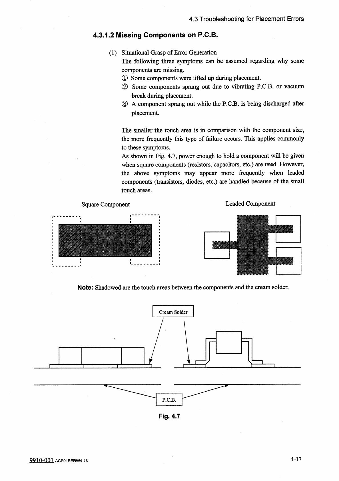
As
shown
in
Fig
.
4.7
,
power
enough
to
hold
a
component
will
be
given
when
square
components
(
resistors
,
capacitors
,
etc
.
)
are
used
.
However
,
the
above
symptoms
may
appear
components
(
transistors
,
diodes
,
etc
.
)
are
handled
because
of
the
small
touch
areas
.
frequently
when
leaded
more
Leaded
Component
Square
Component
Note
:
Shadowed
are
the
touch
areas
between
the
components
and
the
cream
solder
.
Cream
Solder
P
.
C
.
B
.
Fig
.
4.7
4
-
13
9910
-
001
ACP
01
EERW
4
-
13
4.3
Troubleshooting
for
Placement
Errors
(
2
)
Machine
-
Based
Factors
Shown
below
are
the
assumable
main
factors
based
on
the
machine
.
When
trouble
occurs
in
some
of
the
components
(
the
components
of
the
same
type
that
have
been
used
in
the
past
actual
production
)
,
check
for
the
factors
described
in
①
through
⑤
•
①
Worn
,
Clogged
,
or
Dirty
Nozzle
②
Nozzle
Up
/
Down
Movement
Error
③
Flow
Rate
of
Broken
Vacuum
and
Performance
Error
④
Improper
Placement
Height
Level
⑤
Imperfect
Holding
Power
for
P
.
C
.
B
.
Positioning
(
3
)
Other
Factors
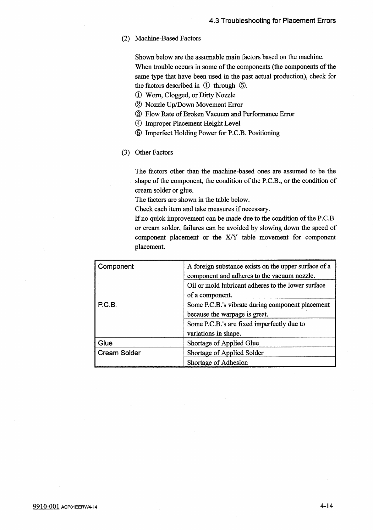
The
factors
other
than
the
machine
-
based
ones
are
assumed
to
be
the
shape
of
the
component
,
the
condition
of
the
P
.
C
.
B
.
,
or
the
condition
of
cream
solder
or
glue
.
The
factors
are
shown
in
the
table
below
.
Check
each
item
and
take
measures
if
necessary
.
If
no
quick
improvement
can
be
made
due
to
the
condition
of
the
P
.
C
.
B
.
or
cream
solder
,
failures
can
be
avoided
by
slowing
down
the
speed
of
component
placement
or
the
X
/
Y
table
movement
for
component
placement
.
A
foreign
substance
exists
on
the
upper
surface
of
a
component
and
adheres
to
the
vacuum
nozzle
.
Component
Oil
or
mold
lubricant
adheres
to
the
lower
surface
of
a
component
.
Some
P
.
C
.
B
.
’
s
vibrate
during
component
placement
because
the
warpage
is
great
.
P
.
C
.
B
.
Some
RC
.
B
.
’
s
are
fixed
imperfectly
due
to
variations
in
shape
.
Glue
Shortage
of
Applied
Glue
Shortage
of
Applied
Solder
Cream
Solder
Shortage
of
Adhesion
4
-
14
9910
-
001
ACP
01
EERW
4
-
14
4.3
Troubleshooting
for
Placement
Errors
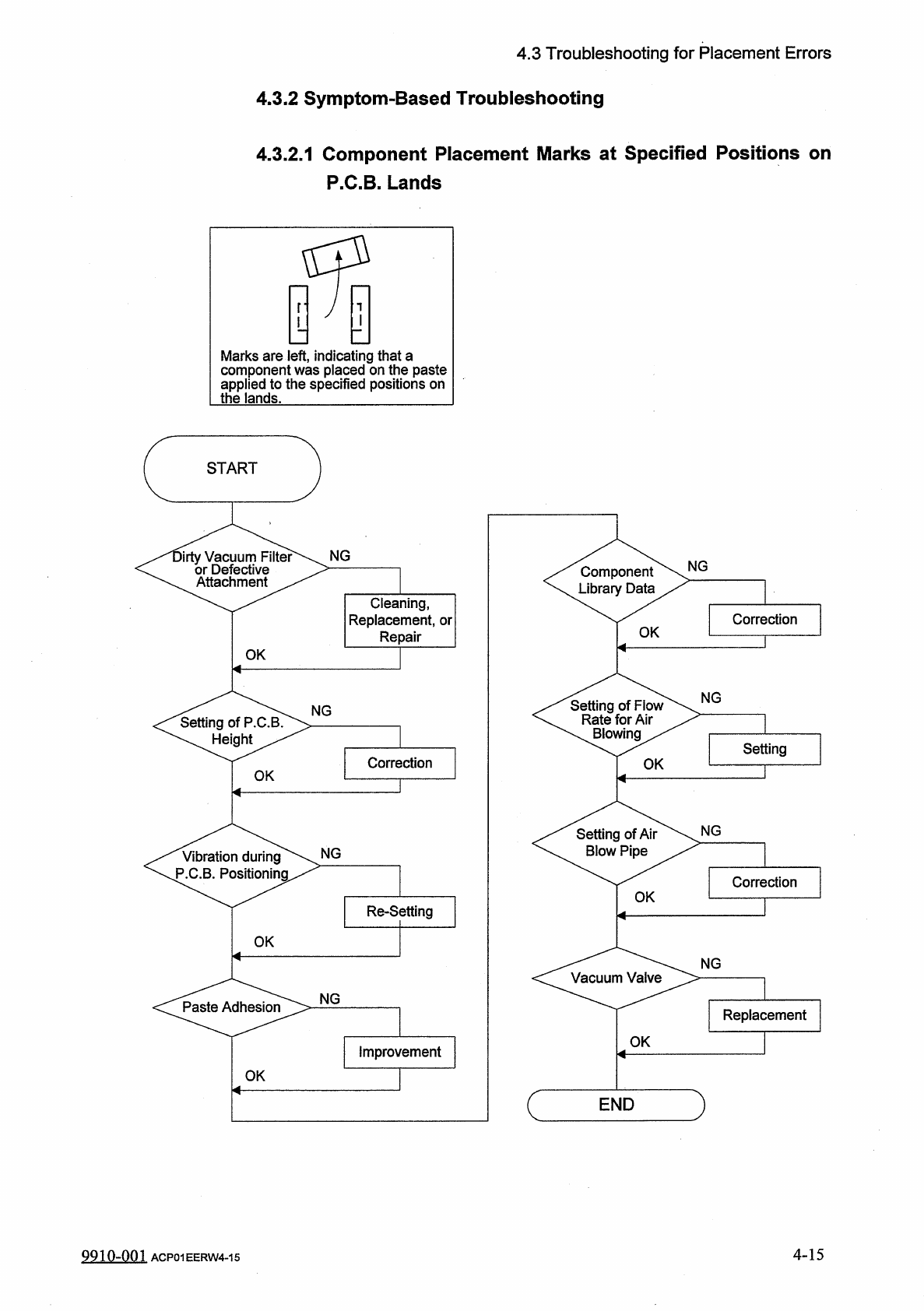
4.3
.
2
Symptom
-
Based
Troubleshooting
4.3
.
2.1
Component
Placement
Marks
at
Specified
Positions
on
P
.
C
.
B
.
Lands
Marks
are
left
,
indicating
that
a
component
was
placed
on
the
paste
applied
to
the
specified
positions
on
the
lands
.
START
NG
irty
Vacuum
Filter
or
Defective
Atta
NG
Component
Library
Data
chment
Cleaning
,
Replacement
,
or
Repair
Correction
OK
OK
<
^
Setting
of
P
.
C
^
^
>
NG
Setting
of
Flow
Rate
for
Air
\
Blowing
/
NG
Setting
Correction
OK
OK
NG
Setting
of
Air
Blow
Pipe
NG
Vibration
during
P
.
C
.
B
.
Positioning
Correction
OK
Re
-
Setting
OK
NG
<
C
^
Pa
^
Ad
^
s
^
^
>
-
NG
Replacement
OK
Improvement
OK
)
END
4
-
15
9910
-
001
ACP
01
EERW
4
-
15