5TROUBLESHOOTING_.pdf - 第26页
2.2 Troubleshooting after Error Display ( C ) ( Display A ) ■ ( Display B ) ■ ( Cause ) - ( Remedy ) Order Code ( Display A ) COMP . PICK - UP ( Z ) AXIS ORIGIN ( Display B ) ENCODER ORIGIN WAS NOT DETECTED . 08 - 01 - 0…
2.2
Troubleshooting
after
Error
Display
(
A
)
(
Display
A
)
•
(
Display
B
)
•
(
Cause
)
-
(
Remedy
)
Order
Code
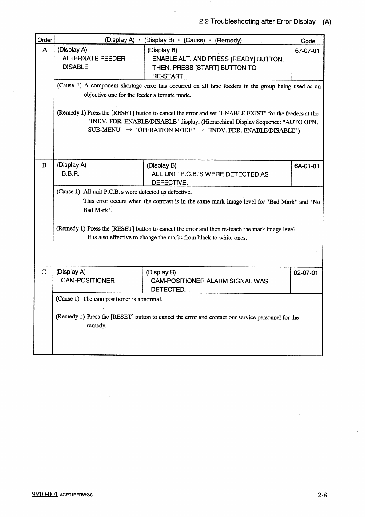
(
Display
A
)
ALTERNATE
FEEDER
DISABLE
(
Display
B
)
ENABLE
ALT
.
AND
PRESS
[
READY
]
BUTTON
.
THEN
,
PRESS
[
START
]
BUTTON
TO
RE
-
START
.
A
67
-
07
-
01
(
Cause
1
)
A
component
shortage
error
has
occurred
on
all
tape
feeders
in
the
group
being
used
objective
one
for
the
feeder
alternate
mode
.
as
an
(
Remedy
1
)
Press
the
[
RESET
]
button
to
cancel
the
error
and
set
”
ENABLE
EXIST
"
for
the
feeders
at
the
"
INDV
.
FDR
.
ENABLE
/
DISABLE
”
display
.
(
Hierarchical
Display
Sequence
:
'
’
AUTO
OPN
.
SUB
-
MENU
1
’
OPERATION
MODE
"
rINDV
.
FDR
.
ENABLE
/
DISABLE
”
)
(
Display
A
)
B
.
B
.
R
.
(
Display
B
)
ALL
UNIT
P
.
C
.
B
/
S
WERE
DETECTED
AS
DEFECTIVE
.
6
A
-
01
-
01
B
(
Cause
1
)
All
unit
P
.
CB
/
s
were
detected
as
defective
.
This
error
occurs
when
the
contrast
is
in
the
same
mark
image
level
for
"
Bad
Mark
”
and
"
No
Bad
Mark
”
.
(
Remedy
1
)
Press
the
[
RESET
]
button
to
cancel
the
error
and
then
re
-
teach
the
mark
image
level
.
It
is
also
effective
to
change
the
marks
from
black
to
white
ones
.
(
Display
A
)
CAM
-
POSITIONER
C
(
Display
B
)
CAM
-
POSITIONER
ALARM
SIGNAL
WAS
DETECTED
.
02
-
07
-
01
(
Cause
1
)
The
cam
positioner
is
abnormal
.
(
Remedy
1
)
Press
the
[
RESET
]
button
to
cancel
the
error
and
contact
our
service
personnel
for
the
remedy
.
9910
-
001
2
-
8
ACP
01
EERW
2
-
8
2.2
Troubleshooting
after
Error
Display
(
C
)
(
Display
A
)
■
(
Display
B
)
■
(
Cause
)
-
(
Remedy
)
Order
Code
(
Display
A
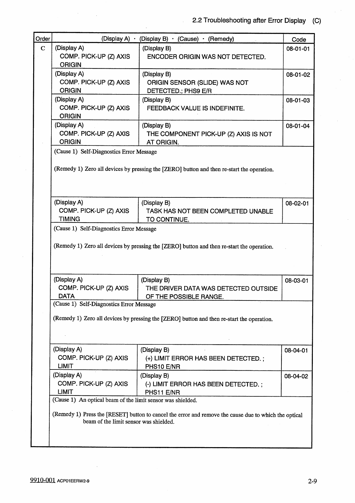
)
COMP
.
PICK
-
UP
(
Z
)
AXIS
ORIGIN
(
Display
B
)
ENCODER
ORIGIN
WAS
NOT
DETECTED
.
08
-
01
-
01
C
(
Display
A
)
COMP
.
PICK
-
UP
(
Z
)
AXIS
ORIGIN
(
Display
B
)
ORIGIN
SENSOR
(
SLIDE
)
WAS
NOT
DETECTED
.
;
PHS
9
E
/
R
08
-
01
-
02
(
Display
A
)
COMP
.
PICK
-
UP
(
Z
)
AXIS
ORIGIN
(
Display
B
)
FEEDBACK
VALUE
IS
INDEFINITE
.
08
-
01
-
03
(
Display
A
)
COMP
.
PICK
-
UP
(
Z
)
AXIS
ORIGIN
(
Display
B
)
THE
COMPONENT
PICK
-
UP
(
Z
)
AXIS
IS
NOT
AT
ORIGIN
.
08
-
01
-
04
(
Cause
1
)
Self
-
Diagnostics
Error
Message
(
Remedy
1
)
Zero
all
devices
by
pressing
the
[
ZERO
]
button
and
then
re
-
start
the
operation
.
(
Display
A
)
COMP
.
PICK
-
UP
(
Z
)
AXIS
TIMING
(
Display
B
)
TASK
HAS
NOT
BEEN
COMPLETED
UNABLE
TO
CONTINUE
.
08
-
02
-
01
(
Cause
1
)
Self
-
Diagnostics
Error
Message
(
Remedy
1
)
Zero
all
devices
by
pressing
the
[
ZERO
]
button
and
then
re
-
start
the
operation
.
(
Display
A
)
COMP
.
PICK
-
UP
(
Z
)
AXIS
DATA
(
Display
B
)
THE
DRIVER
DATA
WAS
DETECTED
OUTSIDE
OF
THE
POSSIBLE
RANGE
.
08
-
03
-
01
(
Cause
1
)
Self
-
Diagnostics
Error
Message
(
Remedy
1
)
Zero
all
devices
by
pressing
the
[
ZERO
]
button
and
then
re
-
start
the
operation
.
(
Display
A
)
COMP
.
PICK
-
UP
(
Z
)
AXIS
LIMIT
(
Display
B
)
(
+
)
LIMIT
ERROR
HAS
BEEN
DETECTED
.
;
PHS
10
E
/
NR
08
-
04
-
01
(
Display
A
)
COMP
.
PICK
-
UP
(
Z
)
AXIS
LIMIT
(
Display
B
)
(
-
)
LIMIT
ERROR
HAS
BEEN
DETECTED
.
;
PHS
11
E
/
NR
08
-
04
-
02
(
Cause
1
)
An
optical
beam
of
the
limit
sensor
was
shielded
.
(
Remedy
1
)
Press
the
[
RESET
]
button
to
cancel
the
error
and
remove
the
cause
due
to
which
the
optical
beam
of
the
limit
sensor
was
shielded
.
9910
-
001
2
-
9
ACP
01
EERW
2
-
9
2.2
Troubleshooting
after
Error
Display
(
C
)
Order
(
Display
A
)
•
(
Display
B
)
•
(
Cause
)
*
(
Remedy
)
Code
(
Display
A
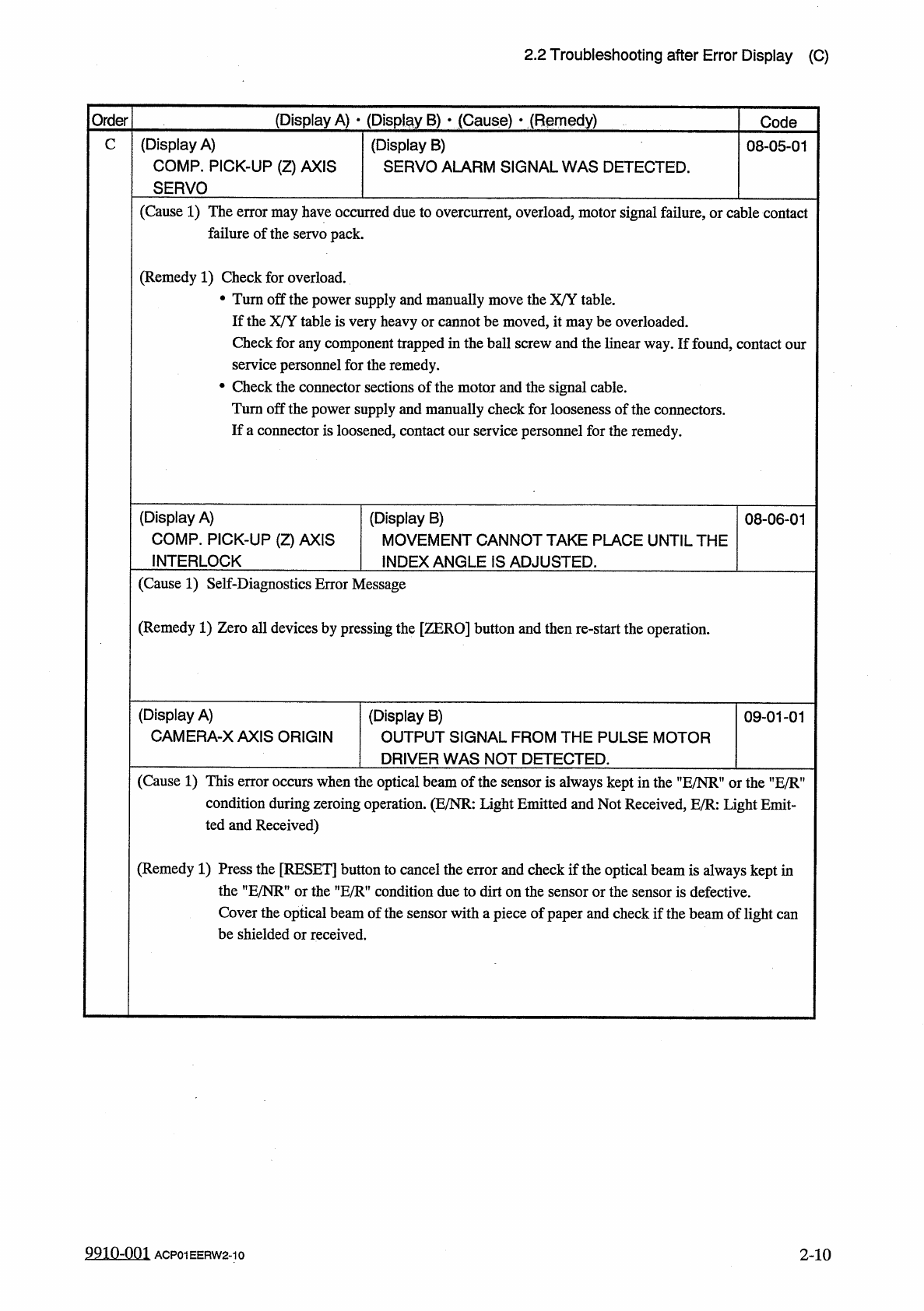
)
COMP
.
PICK
-
UP
(
Z
)
AXIS
SERVO
(
Display
B
)
SERVO
ALARM
SIGNAL
WAS
DETECTED
.
C
08
-
05
-
01
(
Cause
1
)
The
error
may
have
occurred
due
to
overcurrent
,
overload
,
motor
signal
failure
,
or
cable
contact
failure
of
the
servo
pack
.
(
Remedy
1
)
Check
for
overload
.
•
Turn
off
the
power
supply
and
manually
move
the
X
/
Y
table
.
If
the
X
/
Y
table
is
very
heavy
or
cannot
be
moved
,
it
may
be
overloaded
.
Check
for
any
component
trapped
in
the
ball
screw
and
the
linear
way
.
If
found
,
contact
our
service
personnel
for
the
remedy
.
•
Check
the
connector
sections
of
the
motor
and
the
signal
cable
.
Turn
off
the
power
supply
and
manually
check
for
looseness
of
the
connectors
.
If
a
connector
is
loosened
,
contact
our
service
personnel
for
the
remedy
.
(
Display
A
)
COMP
.
PICK
-
UP
(
Z
)
AXIS
INTERLOCK
(
Display
B
)
MOVEMENT
CANNOT
TAKE
PLACE
UNTIL
THE
INDEX
ANGLE
IS
ADJUSTED
.
08
-
06
-
01
(
Cause
1
)
Self
-
Diagnostics
Error
Message
(
Remedy
1
)
Zero
all
devices
by
pressing
the
[
ZERO
]
button
and
then
re
-
start
the
operation
.
(
Display
A
)
CAMERA
-
XAXIS
ORIGIN
(
Display
B
)
OUTPUT
SIGNAL
FROM
THE
PULSE
MOTOR
DRIVER
WAS
NOT
DETECTED
.
09
-
01
-
01
(
Cause
1
)
This
error
occurs
when
the
optical
beam
of
the
sensor
is
always
kept
in
the
"
E
/
NR
"
or
the
HE
/
R
?
condition
during
zeroing
operation
.
(
E
/
NR
:
Light
Emitted
and
Not
Received
,
E
/
R
:
Light
Emit
-
ted
and
Received
)
(
Remedy
1
)
Press
the
[
RESET
]
button
to
cancel
the
error
and
check
if
the
optical
beam
is
always
kept
in
the
"
E
/
NR
”
or
the
"
E
/
R
"
condition
due
to
dirt
on
the
sensor
or
the
sensor
is
defective
.
Cover
the
optical
beam
of
the
sensor
with
a
piece
of
paper
and
check
if
the
beam
of
light
can
be
shielded
or
received
.
9910
-
001
ACP
01
EERW
2
-
10
2
-
10