5TROUBLESHOOTING_.pdf - 第35页
2.2 Troubleshooting after Error Display ( C ) ( Display A ) • ( Display B ) • ( Cause ) • ( Remedy ) Order Code ( Display A ) COMP . THICKNESS C ( Display B ) " STEP " AND " LANE " ARE DISPLAYED . 67 …
2.2
Troubleshooting
after
Error
Display
(
C
)
Order
(
Display
A
)
•
(
Display
B
)
y
(
Cause
)
>
(
Remedy
)
Code
C
(
Display
A
)
COMP
.
MISSING
(
RECOG
.
)
(
Display
B
)
"
STEP
"
AND
"
LANE
"
ARE
DISPLAYED
.
67
-
03
(
Cause
1
)
The
machine
stopped
running
because
the
component
recognition
camera
detected
the
,
f
Com
-
ponent
Missing
(
Recognition
)
”
error
continuously
.
Ref
.
:
When
"
9
"
is
set
in
the
"
ERROR
PROCESS
DATA
T
text
box
in
the
component
library
data
,
it
means
that
a
pick
-
up
error
occurred
continuously
9
times
on
the
same
lane
(
feed
-
er
slot
No
.
)
.
(
Remedy
1
)
Follow
the
steps
below
to
reset
the
machine
to
the
normal
condition
.
(
1
)
Check
"
Step
”
and
”
Lane
"
in
the
"
(
Display
(
2
)
Press
the
[
RESET
]
button
and
then
the
[
items
related
to
the
pertinent
lane
(
feeder
slot
No
.
)
.
•
Check
if
some
components
are
left
in
the
tape
feeder
.
•
Check
if
the
cover
tape
is
peeled
off
normally
.
•
Check
if
the
tape
feeder
is
installed
correctly
on
the
feeder
carriage
.
•
Check
if
the
tape
feeder
is
loaded
with
correct
components
.
•
Check
if
some
components
are
left
in
the
carrier
tape
.
If
left
,
be
sure
to
remove
them
to
protect
the
cutter
blades
from
being
damaged
.
•
Check
if
the
vacuum
nozzle
is
not
clogged
or
proper
vacuum
pressure
is
applied
.
(
3
)
After
taking
the
required
countermeasures
,
re
-
start
the
production
.
BY
field
.
ZERO
]
button
.
After
that
,
check
the
following
(
Display
A
)
COMP
.
RECOG
.
ERROR
(
Display
B
)
"
STEP
"
AND
"
LANE
"
ARE
DISPLAYED
.
67
-
04
(
Cause
1
)
The
machine
stopped
running
because
the
component
recognition
camera
detected
the
M
Com
-
ponent
Recognition
Error
(
Recognition
)
"
error
continuously
.
Ref
.
:
When
"
9
”
is
set
in
the
”
ERROR
PROCESS
DATA
T
text
box
in
the
component
library
data
,
it
means
that
a
pick
-
up
error
occurred
continuously
9
times
on
the
same
lane
(
feed
-
er
slot
No
.
)
.
(
Remedy
1
)
Follow
the
steps
below
to
reset
the
machine
to
the
normal
condition
.
(
1
)
Check
"
Step
”
and
"
Lane
”
in
the
"
(
Display
B
)
(
2
)
Press
the
[
RESET
]
button
and
then
the
[
ZERO
]
button
.
After
that
,
check
the
following
items
related
to
the
pertinent
lane
(
feeder
slot
No
.
)
.
•
Check
if
the
tape
feeder
is
loaded
with
correct
components
.
•
Check
the
selected
components
and
the
component
library
data
.
If
wrong
parameters
are
set
in
the
component
library
data
,
correct
them
.
(
3
)
After
taking
the
required
countermeasures
,
re
-
start
the
production
.
field
.
2
-
17
9910
-
001
ACP
01
EERW
2
-
17
2.2
Troubleshooting
after
Error
Display
(
C
)
(
Display
A
)
•
(
Display
B
)
•
(
Cause
)
•
(
Remedy
)
Order
Code
(
Display
A
)
COMP
.
THICKNESS
C
(
Display
B
)
"
STEP
"
AND
"
LANE
"
ARE
DISPLAYED
.
67
-
08
(
SENSOR
)
(
Cause
1
)
The
machine
stopped
running
because
the
linear
measure
sensor
detected
the
Component
Thickness
Error
(
Sensor
)
"
error
continuously
.
Ref
.
:
When
"
9
”
is
set
in
the
"
ERROR
PROCESS
DATA
2
,
f
text
box
in
the
component
library
data
,
it
means
that
a
pick
-
up
error
occurred
continuously
9
times
on
the
same
lane
(
feed
-
er
slot
No
.
)
.
(
Remedy
1
)
Follow
the
steps
below
to
reset
the
machine
to
the
normal
condition
.
⑴
Check
"
Step
”
and
"
Lane
”
in
the
"
(
Display
B
)
"
field
.
(
2
)
Press
the
[
RESET
]
button
and
then
the
[
ZERO
]
button
.
After
that
,
check
the
following
items
related
to
the
pertinent
lane
(
feeder
slot
No
.
)
.
•
Check
if
the
tape
feeder
is
loaded
with
correct
components
.
•
Check
the
selected
components
and
the
component
library
data
.
'
If
wrong
parameters
are
set
in
the
component
library
data
,
correct
them
.
Note
:
Check
the
parameter
set
as
"
Component
Thickness
Check
"
data
at
the
"
COMP
.
CARRIAGE
DATA
EDIT
"
display
.
(
3
)
After
taking
the
required
countermeasures
,
re
-
start
the
production
.
(
Display
A
)
CARRIAGE
READY
(
Display
B
)
THE
CARRIAGE
#
1
IS
NOT
READY
.
(
HOME
POSITION
)
68
-
02
-
01
(
Display
A
)
CARRIAGE
READY
(
Display
B
)
THE
CARRIAGE
#
2
IS
NOT
READY
.
(
HOME
POSITION
)
68
-
02
-
02
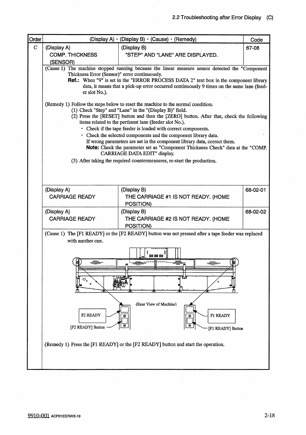
(
Cause
1
)
The
[
FI
READY
]
or
the
[
F
2
READY
]
button
was
not
pressed
after
a
tape
feeder
was
replaced
with
another
one
.
F
2
READY
FI
READY
[
F
2
READY
]
Button
[
FI
READY
]
Button
(
Remedy
1
)
Press
the
[
FI
READY
]
or
the
[
F
2
READY
]
button
and
start
the
operation
.
2
-
18
9910
-
001
ACP
01
EERW
2
-
18
2.2
Troubleshooting
after
Error
Display
(
C
)
(
Display
A
)
•
(
Display
B
)
•
(
Cause
)
•
(
Remedy
)
Order
Code
(
Display
A
)
COMPONENT
PLACEMENT
C
(
Display
B
)
THERE
ISA
POSSIBILITY
OF
A
MISS
MOUNT
.
68
-
07
-
01
CHECK
P
.
C
.
B
,
ON
XY
-
TABLE
.
(
Cause
1
)
A
placement
error
may
have
occurred
.
(
Remedy
1
)
Check
the
cause
and
take
the
required
countermeasures
.
Then
,
start
the
production
.
(
Display
A
)
COMP
.
RECOG
.
TEST
xxxxxxxx
(
Display
B
)
Note
69
-
01
Note
Note
:
Refer
to
”
3.3
.
1
Reset
Procedure
from
Component
Recognition
Error
”
for
the
detailed
error
display
.
(
Display
A
)
COMP
.
THICKNESS
TEACH
(
Display
B
)
COMPONENT
THICKNESS
WAS
LESS
THEN
TOLERANCE
.
70
76
-
07
-
01
(
Display
A
)
COMP
.
THICKNESS
TEACH
(
Display
B
)
COMPONENT
THICKNESS
WAS
MORE
THEN
TOLERANCE
.
70
76
-
07
-
02
(
Cause
1
)
A
mistake
is
found
in
the
component
thickness
data
of
the
component
library
data
.
(
Remedy
1
)
Set
the
component
thickness
data
correctly
.
(
Display
A
)
CAMERA
-
Y
AXIS
ORIGIN
(
Display
B
)
OUTPUT
SIGNAL
FROM
THE
PULSE
MOTOR
0
A
-
01
-
01
DRIVER
WAS
NOT
DETECTED
.
(
Cause
1
)
This
error
occurs
when
the
optical
beam
of
the
sensor
is
always
kept
in
the
"
E
/
NR
”
or
the
”
E
/
R
”
condition
during
zeroing
operation
.
(
E
/
NR
:
Light
Emitted
and
Not
Received
E
/
R
:
Light
Emit
-
ted
and
Received
)
(
Remedy
1
)
Press
the
[
RESET
]
button
to
cancel
the
error
and
check
if
the
optical
beam
is
always
kept
in
the
”
E
/
NR
”
or
the
,
,
E
/
R
?
,
condition
due
to
dirt
on
the
sensor
or
the
sensor
is
defective
.
Cover
the
optical
beam
of
the
sensor
with
a
piece
of
paper
and
check
if
the
beam
can
be
shielded
or
received
.
2
-
19
9910
-
001
ACP
01
EERW
2
-
19