5TROUBLESHOOTING_.pdf - 第38页
2.2 Troubleshooting after Error Display ( C ) ( Display A ) • ( Display B ) • ( Cause ) * ( Remedy ) Order Code ( Display A ) CAMERA - X AXIS DATA ( Display B ) THE DRIVER DATA WAS DETECTED OUTSIDE OF THE POSSIBLE RANGE …
2.2
Troubleshooting
after
Error
Display
(
C
)
(
Display
A
)
•
(
Display
B
)
•
(
Cause
)
•
(
Remedy
)
Order
Code
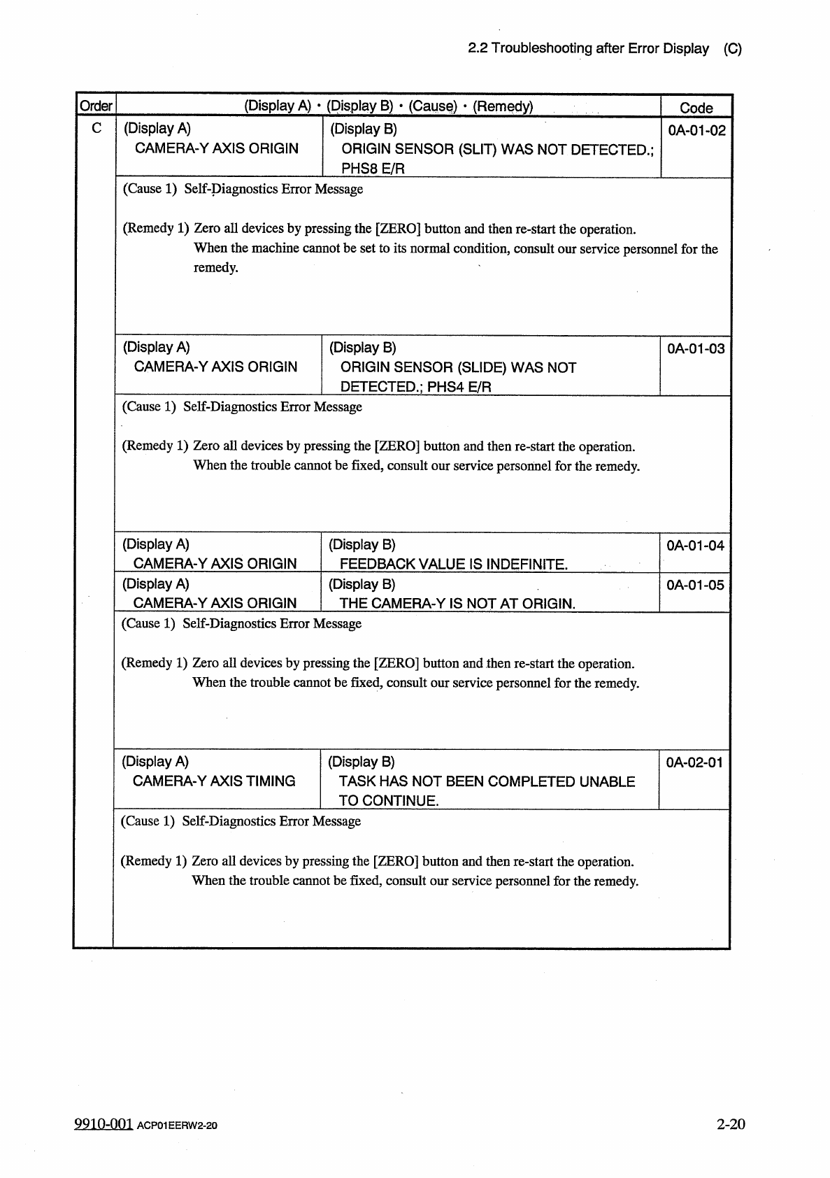
(
Display
A
)
CAMERA
-
YAXIS
ORIGIN
(
Display
B
)
ORIGIN
SENSOR
(
SLIT
)
WAS
NOT
DETECTED
.
;
PHS
8
E
/
R
C
0
A
-
01
-
02
(
Cause
1
)
Self
-
piagnostics
Error
Message
(
Remedy
1
)
Zero
all
devices
by
pressing
the
[
ZERO
]
button
and
then
re
-
start
the
operation
.
When
the
machine
cannot
be
set
to
its
normal
condition
,
consult
our
service
personnel
for
the
remedy
.
(
Display
A
)
CAMERA
-
YAXIS
ORIGIN
(
Display
B
)
ORIGIN
SENSOR
(
SLIDE
)
WAS
NOT
DETECTED
.
;
PHS
4
E
/
R
0
A
-
01
-
03
(
Cause
1
)
Self
-
Diagnostics
Error
Message
(
Remedy
1
)
Zero
all
devices
by
pressing
the
[
ZERO
]
button
and
then
re
-
start
the
operation
.
When
the
trouble
cannot
be
fixed
,
consult
our
service
personnel
for
the
remedy
.
(
Display
A
)
CAMERA
-
YAXIS
ORIGIN
(
Display
B
)
FEEDBACK
VALUE
IS
INDEFINITE
.
0
A
-
01
-
04
(
Display
A
)
CAMERA
-
Y
AXIS
ORIGIN
(
Display
B
)
THE
CAMERA
-
Y
IS
NOT
AT
ORIGIN
.
0
A
-
01
-
05
(
Cause
1
)
Self
-
Diagnostics
Error
Message
(
Remedy
1
)
Zero
all
devices
by
pressing
the
[
ZERO
]
button
and
then
re
-
start
the
operation
.
When
the
trouble
cannot
be
fixed
,
consult
our
service
personnel
for
the
remedy
.
(
Display
A
)
CAMERA
-
Y
AXIS
TIMING
(
Display
B
)
TASK
HAS
NOT
BEEN
COMPLETED
UNABLE
TO
CONTINUE
.
0
A
-
02
-
01
(
Cause
1
)
Self
-
Diagnostics
Error
Message
(
Remedy
1
)
Zero
all
devices
by
pressing
the
[
ZERO
]
button
and
then
re
-
start
the
operation
.
When
the
trouble
cannot
be
fixed
,
consult
our
service
personnel
for
the
remedy
.
2
-
20
9910
-
001
ACP
01
EERW
2
-
20
2.2
Troubleshooting
after
Error
Display
(
C
)
(
Display
A
)
•
(
Display
B
)
•
(
Cause
)
*
(
Remedy
)
Order
Code
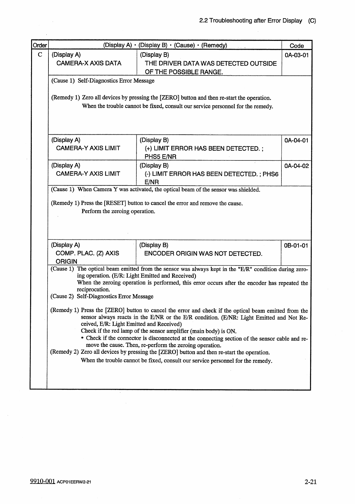
(
Display
A
)
CAMERA
-
X
AXIS
DATA
(
Display
B
)
THE
DRIVER
DATA
WAS
DETECTED
OUTSIDE
OF
THE
POSSIBLE
RANGE
.
0
A
-
03
-
01
C
(
Cause
1
)
Self
-
Diagnostics
Error
Message
(
Remedy
1
)
Zero
all
devices
by
pressing
the
[
ZERO
]
button
and
then
re
-
start
the
operation
.
When
the
trouble
cannot
be
fixed
,
consult
our
service
personnel
for
the
remedy
.
(
Display
A
)
CAMERA
-
YAXIS
LIMIT
(
Display
B
)
(
+
)
LIMIT
ERROR
HAS
BEEN
DETECTED
.
:
PHS
5
E
/
NR
0
A
-
04
-
01
(
Display
A
)
CAMERA
-
YAXIS
LIMIT
(
Display
B
)
(
-
)
LIMIT
ERROR
HAS
BEEN
DETECTED
.
;
PHS
6
E
/
NR
0
A
-
04
-
02
(
Cause
1
)
When
Camera
Y
was
activated
,
the
optical
beam
of
the
sensor
was
shielded
.
(
Remedy
1
)
Press
the
[
RESET
]
button
to
cancel
the
error
and
remove
the
cause
.
Perform
the
zeroing
operation
.
(
Display
A
)
COMP
.
PLAC
.
(
Z
)
AXIS
ORIGIN
(
Display
B
)
ENCODER
ORIGIN
WAS
NOT
DETECTED
.
0
B
-
01
-
01
(
Cause
1
)
The
optical
beam
emitted
from
the
sensor
was
always
kept
in
the
"
E
/
Rn
condition
during
ing
operation
.
(
E
/
R
:
Light
Emitted
and
Received
)
When
the
zeroing
operation
is
performed
,
this
error
occurs
after
the
encoder
has
repeated
the
reciprocation
.
(
Cause
2
)
Self
-
Diagnostics
Error
Message
(
Remedy
1
)
Press
the
[
ZERO
]
button
to
cancel
the
error
and
check
if
the
optical
beam
emitted
from
the
sensor
always
reacts
in
the
E
/
NR
or
the
E
/
R
condition
.
(
E
/
NR
:
Light
Emitted
and
Not
Re
-
ceived
,
E
/
R
:
light
Emitted
and
Received
)
Check
if
the
red
lamp
of
the
sensor
amplifier
(
main
body
)
is
ON
.
•
Check
if
the
connector
is
disconnected
at
the
connecting
section
of
the
sensor
cable
and
re
-
move
the
cause
.
Then
,
re
-
perform
the
zeroing
operation
.
(
Remedy
2
)
Zero
all
devices
by
pressing
the
[
ZERO
]
button
and
then
re
-
start
the
operation
.
When
the
trouble
cannot
be
fixed
,
consult
our
service
personnel
for
the
remedy
.
9910
-
001
ACP
01
EERW
2
-
21
2
-
21
2.2
Troubleshooting
after
Error
Display
(
C
)
(
Display
A
)
•
(
Display
B
)
•
(
Cause
)
*
(
Remedy
)
Order
Code
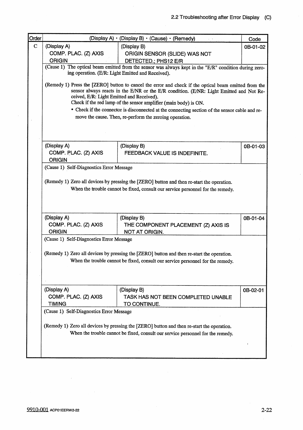
(
Display
A
)
COMP
.
PLAC
.
(
Z
)
AXIS
ORIGIN
(
Display
B
)
ORIGIN
SENSOR
(
SLIDE
)
WAS
NOT
DETECTED
.
;
PHS
12
E
/
R
C
0
B
-
01
-
02
(
Cause
1
)
The
optical
beam
emitted
from
the
sensor
was
always
kept
in
the
"
E
/
R
”
condition
during
zero
-
ing
operation
.
(
E
/
R
:
Light
Emitted
and
Received
)
.
(
Remedy
1
)
Press
the
[
ZERO
]
button
to
cancel
the
error
and
check
if
the
optical
beam
emitted
from
the
sensor
always
reacts
in
the
E
/
NR
or
the
E
/
R
condition
.
(
E
/
NR
:
Light
Emitted
and
Not
Re
-
ceived
,
E
/
R
:
light
Emitted
and
Received
)
.
Check
if
the
red
lamp
of
the
sensor
amplifier
(
main
body
)
is
ON
.
•
Check
if
the
connector
is
disconnected
at
the
connecting
section
of
the
sensor
cable
and
re
-
move
the
cause
.
Then
,
re
-
perform
the
zeroing
operation
.
(
Display
A
)
COMP
.
PLAC
.
(
Z
)
AXIS
ORIGIN
(
Display
B
)
FEEDBACK
VALUE
IS
INDEFINITE
.
0
B
-
01
-
03
(
Cause
1
)
Self
-
Diagnostics
Error
Message
(
Remedy
1
)
Zero
all
devices
by
pressing
the
[
ZERO
]
button
and
then
re
-
start
the
operation
.
When
the
trouble
cannot
be
fixed
,
consult
our
service
personnel
for
the
remedy
.
(
Display
A
)
COMP
.
PLAC
.
(
Z
)
AXIS
ORIGIN
(
Display
B
)
THE
COMPONENT
PLACEMENT
(
Z
)
AXIS
IS
NOT
AT
ORIGIN
.
0
B
-
01
-
04
(
Cause
1
)
Self
-
Diagnostics
Error
Message
(
Remedy
1
)
Zero
all
devices
by
pressing
the
[
ZERO
]
button
and
then
re
-
start
the
operation
.
When
the
trouble
cannot
be
fixed
,
consult
our
service
personnel
for
the
remedy
.
(
Display
A
)
COMP
.
PLAC
.
(
Z
)
AXIS
TIMING
(
Display
B
)
TASK
HAS
NOT
BEEN
COMPLETED
UNABLE
TO
CONTINUE
.
0
B
-
02
-
01
(
Cause
1
)
Self
-
Diagnostics
Error
Message
(
Remedy
1
)
Zero
all
devices
by
pressing
the
[
ZERO
]
button
and
then
re
-
start
the
operation
.
When
the
trouble
cannot
be
fixed
,
consult
our
service
personnel
for
the
remedy
.
9910
-
001
ACP
01
EERW
2
-
22
2
-
22