5TROUBLESHOOTING_.pdf - 第47页
2.2 Troubleshooting after Error Display ( F ) ( Display A ) • ( Display B ) • ( Cause ) • ( Remedy ) Order Code 63 - 06 - 01 F ( Display A ) FDR . CRG . AXIS MOTOR ( Display B ) FDR . CRG . AXIS MOTOR # 1 & # 2 HAVE …
2.2
Troubleshooting
after
Error
Display
(
F
)
(
Display
A
)
•
(
Display
B
)
•
(
Cause
)
-
(
Remedy
)
Order
Code
(
Display
A
)
FDR
.
CRG
.
AXIS
MOTOR
#
2
INTERLOCK
(
Display
B
)
MOVEMENT
CANNOT
TAKE
PLACE
UNTIL
THE
INDEX
ANGLE
IS
ADJUSTED
.
F
07
-
06
-
01
(
Display
A
)
FDR
.
CRG
.
AXIS
MOTOR
#
2
INTERLOCK
(
Display
B
)
PALLET
WENT
OUT
.
07
-
06
-
02
(
Cause
1
)
Self
-
Diagnostics
Error
Message
(
Remedy
1
)
Zero
all
devices
by
pressing
the
[
ZERO
]
button
and
then
re
-
start
the
operation
.
When
the
trouble
cannot
be
fixed
,
consult
our
service
personnel
for
the
remedy
.
(
Display
A
)
FDR
.
CRG
.
AXIS
SAFETY
GUARD
(
Display
B
)
THE
FDR
.
CRG
.
#
1
HOME
LOCATION
SAFETY
GUARD
IS
OPEN
.
;
LS
9
OFF
60
-
02
-
01
(
Display
A
)
FDR
,
CRG
.
AXIS
SAFETY
GUARD
(
Display
B
)
THE
FDR
.
CRG
.
#
2
HOME
LOCATION
SAFETY
60
-
02
-
02
GUARD
IS
OPEN
.
;
LS
10
OFF
(
Cause
1
)
The
safety
cover
was
opened
while
Feeder
Carriage
#
1
or
#
2
was
moving
.
(
Cause
2
)
The
[
START
]
button
was
pressed
with
the
safety
cover
being
open
.
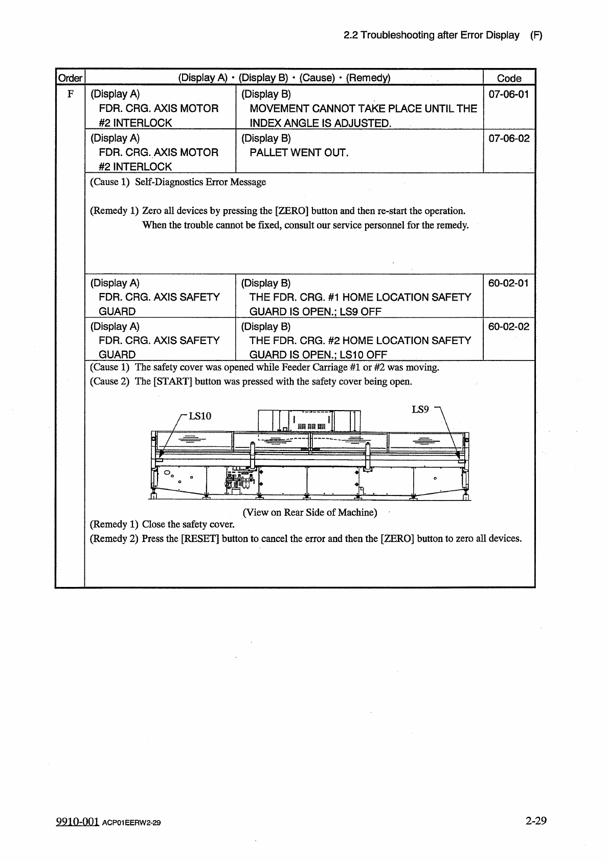
LS
9
LS
10
苜目目自匪
丄 崎
~
T
—
~
'
Tp
2
E
(
View
on
Rear
Side
of
Machine
)
(
Remedy
1
)
Close
the
safety
cover
.
(
Remedy
2
)
Press
the
[
RESET
]
button
to
cancel
the
error
and
then
the
[
ZERO
]
button
to
zero
all
devices
.
2
-
29
9910
-
001
ACP
01
EERW
2
-
29
2.2
Troubleshooting
after
Error
Display
(
F
)
(
Display
A
)
•
(
Display
B
)
•
(
Cause
)
•
(
Remedy
)
Order
Code
63
-
06
-
01
F
(
Display
A
)
FDR
.
CRG
.
AXIS
MOTOR
(
Display
B
)
FDR
.
CRG
.
AXIS
MOTOR
#
1
&
#
2
HAVE
COLLIDED
.
;
LS
2
(
Cause
1
)
Dirt
adheres
to
the
sensor
and
the
optical
beam
is
shielded
.
(
Cause
2
)
The
sensor
position
maybe
wrong
or
the
sensor
maybe
defective
.
The
servo
pack
may
be
defective
.
(
Remedy
1
)
Follow
the
steps
below
to
reset
the
machine
from
the
error
condition
.
Notes
:
Use
only
the
rear
touch
panel
for
operations
.
No
operations
on
the
front
touch
panel
are
possible
.
(
1
)
Press
the
[
RESET
]
button
.
The
"
FEEDER
CARRIAGE
COLLISION
ERROR
"
display
appears
on
the
screen
.
Wipe
off
dirt
on
the
sensor
before
performing
the
reset
operation
.
Follow
the
instructions
described
in
this
display
for
the
reset
operation
.
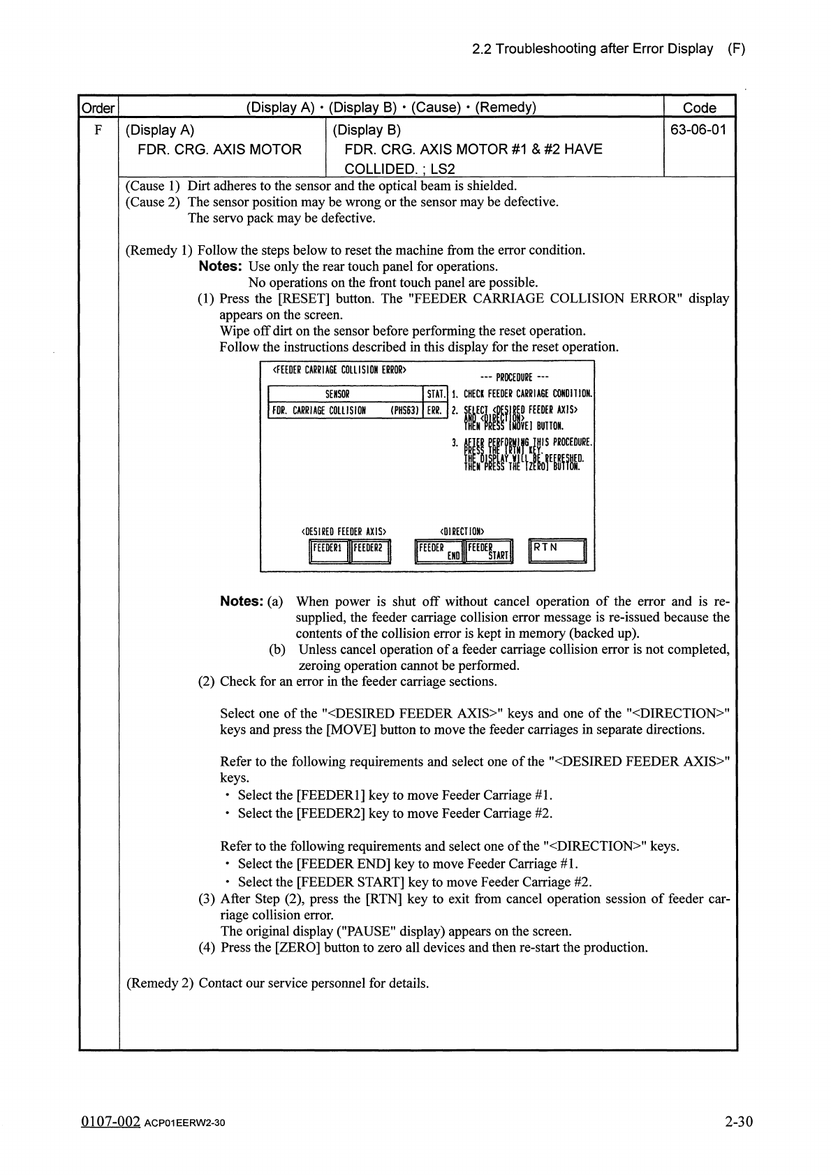
《
FEEDER
CARRIAGE
COLLISION
ERROR
)
一
PROCEDURE
—
STAlll
.
CHECK
FEEDER
CARRIAGE
CONDI
110
N
EDER
AX
1
S
>
BUTTON
.
SENSOR
m
.
CARRIAGE
COLLISION
(
PHS
63
)
ERR
.
〈
DESIRED
FEEDER
AX
1
S
>
〈
DIRECTI
0
M
>
1
圓
卜
1
ttFEEDEeEND
«
lFEED
£
Ul
Notes
:
(
a
)
When
power
is
shut
off
without
cancel
operation
of
the
error
and
is
re
-
supplied
,
the
feeder
carriage
collision
error
message
is
re
-
issued
because
the
contents
of
the
collision
error
is
kept
in
memory
(
backed
up
)
.
(
b
)
Unless
cancel
operation
of
a
feeder
carriage
collision
error
is
not
completed
,
zeroing
operation
cannot
be
performed
.
(
2
)
Check
for
an
error
in
the
feeder
carriage
sections
.
Select
one
of
the
"
〈
DESIRED
FEEDER
AXIS
〉
"
keys
and
one
of
the
"
〈
DIRECTION
〉
"
keys
and
press
the
[
MOVE
]
button
to
move
the
feeder
carriages
in
separate
directions
.
Refer
to
the
following
requirements
and
select
one
of
the
"
〈
DESIRED
FEEDER
AXIS
〉
"
keys
.
•
Select
the
[
FEEDER
1
]
key
to
move
Feeder
Carriage
#
1
.
•
Select
the
[
FEEDER
2
]
key
to
move
Feeder
Carriage
#
2
.
Refer
to
the
following
requirements
and
select
one
of
the
"
<
DIRECTION
>
"
keys
.
•
Select
the
[
FEEDER
END
]
key
to
move
Feeder
Carriage
#
1
.
•
Select
the
[
FEEDER
START
]
key
to
move
Feeder
Carriage
#
2
.
(
3
)
After
Step
(
2
)
,
press
the
[
RTN
]
key
to
exit
from
cancel
operation
session
of
feeder
car
-
riage
collision
error
.
The
original
display
(
"
PAUSE
"
display
)
appears
on
the
screen
.
(
4
)
Press
the
[
ZERO
]
button
to
zero
all
devices
and
then
re
-
start
the
production
.
(
Remedy
2
)
Contact
our
service
personnel
for
details
.
0107
-
002
ACP
01
EERW
2
-
30
2
-
30
2.2
Troubleshooting
after
Error
Display
(
F
)
(
Display
A
)
•
(
Display
B
)
•
(
Cause
)
•
(
Remedy
)
Code
Order
(
Display
A
)
FEEDER
SET
(
Display
B
)
THE
FDR
.
MIS
-
SET
TEMPLATE
(
C
1
SIDE
)
HAS
BEEN
DETECTED
.
;
PXS
17
QN
(
Display
B
)
THE
FDR
.
MIS
-
SET
TEMPLATE
(
C
2
SIDE
)
HAS
BEEN
DETECTED
.
;
PXS
18
QN
63
-
07
-
01
F
63
-
07
-
02
(
Display
A
)
FEEDER
SET
(
Display
A
)
FEEDER
SET
(
Display
B
)
THE
FDR
.
IDX
.
LEVER
(
C
1
SIDE
)
HAS
BEEN
DETECTED
.
;
PXS
19
ON
63
-
07
-
03
(
Display
A
)
FEEDER
SET
(
Display
B
)
THE
FDR
.
IDX
.
LEVER
(
C
2
SIDE
)
HAS
BEEN
DETECTED
.
;
PXS
20
ON
63
-
07
-
04
(
Display
A
)
FEEDER
SET
(
Display
B
)
THE
FDR
.
MIS
-
SET
BAR
(
C
1
SIDE
)
HAS
BEEN
DETECTED
.
;
LS
5
ON
63
-
07
-
05
(
Display
A
)
FEEDER
SET
(
Display
B
)
THE
FDR
.
MIS
-
SET
BAR
(
C
2
SIDE
)
HAS
BEEN
DETECTED
.
;
LS
6
ON
63
-
07
-
06
(
Display
A
)
FEEDER
SET
(
Display
B
)
THE
FDR
.
MIS
-
SET
HOLDER
(
C
1
SIDE
)
HAS
BEEN
DETECTED
.
;
PXS
22
ON
63
-
07
-
07
(
Display
A
)
FEEDER
SET
(
Display
B
)
THE
FDR
.
MIS
-
SET
HOLDER
(
C
2
SIDE
)
HAS
63
-
07
-
08
BEEN
DETECTED
.
;
PXS
23
ON
(
Cause
1
)
The
tape
feeder
is
not
correctly
installed
on
the
feeder
carriage
.
•
The
tape
feeder
was
lifted
afloat
and
touched
the
detection
photosensor
.
•
The
tape
feeder
touched
the
detection
photosensor
because
it
was
deformed
.
•
The
tape
feeder
touched
the
detection
photosensor
because
it
is
not
for
the
TCM
-
3000
series
.
•
The
hook
of
the
tape
feeder
was
not
locked
and
the
hook
or
the
suppressor
touched
the
detec
-
tion
photosensor
.
•
The
tape
end
touched
the
detection
photosensor
because
it
was
long
.
,
Feeder
Mis
-
Set
Bar
Detection
(
Cl
Side
)
(
LS
5
)
Feeder
Mis
-
Set
Bar
Detection
(
C
2
Side
)
(
LS
6
)
Feeder
Mis
-
Set
Template
(
Cl
side
)
(
PXS
17
)
Feeder
Mis
-
Set
Template
(
C
2
Side
)
(
PXS
18
)
Feeder
Index
Lever
Detection
(
Cl
Side
)
(
PXS
19
)
Feeder
Mis
-
Set
Detection
(
Cl
Side
)
(
PXS
22
)
Feeder
Index
Lever
Detection
(
C
2
Side
)
(
PXS
20
)
Feeder
Mis
-
Set
Detection
(
C
2
Side
)
(
PXS
23
)
(
View
from
Rear
Side
of
Machine
)
(
Continued
to
the
next
pa
^
e
)
9910
-
001
ACP
01
EERW
2
-
31
2
-
31