5TROUBLESHOOTING_.pdf - 第50页
2.2 Troubleshooting after Error Display ( F ) ( Display A ) • ( Display B ) • ( Cause ) • ( Remedy ) Order Code ( Display A ) THE FEEDER INDEX F ( Display B ) THE STRUCTURE OF FEEDER INDEX LEVER # 2 WAS NOT ACTIVATED . ;…
2.2
Troubleshooting
after
Error
Display
(
F
)
(
Display
A
)
•
(
Display
B
)
•
(
Cause
)
•
(
Remedy
)
Order
Code
(
Remedy
1
)
Follow
the
steps
below
to
reset
the
machine
from
the
error
condition
.
Notes
:
Use
only
the
rear
touch
panel
for
operations
.
No
operations
on
the
front
touch
panel
are
possible
.
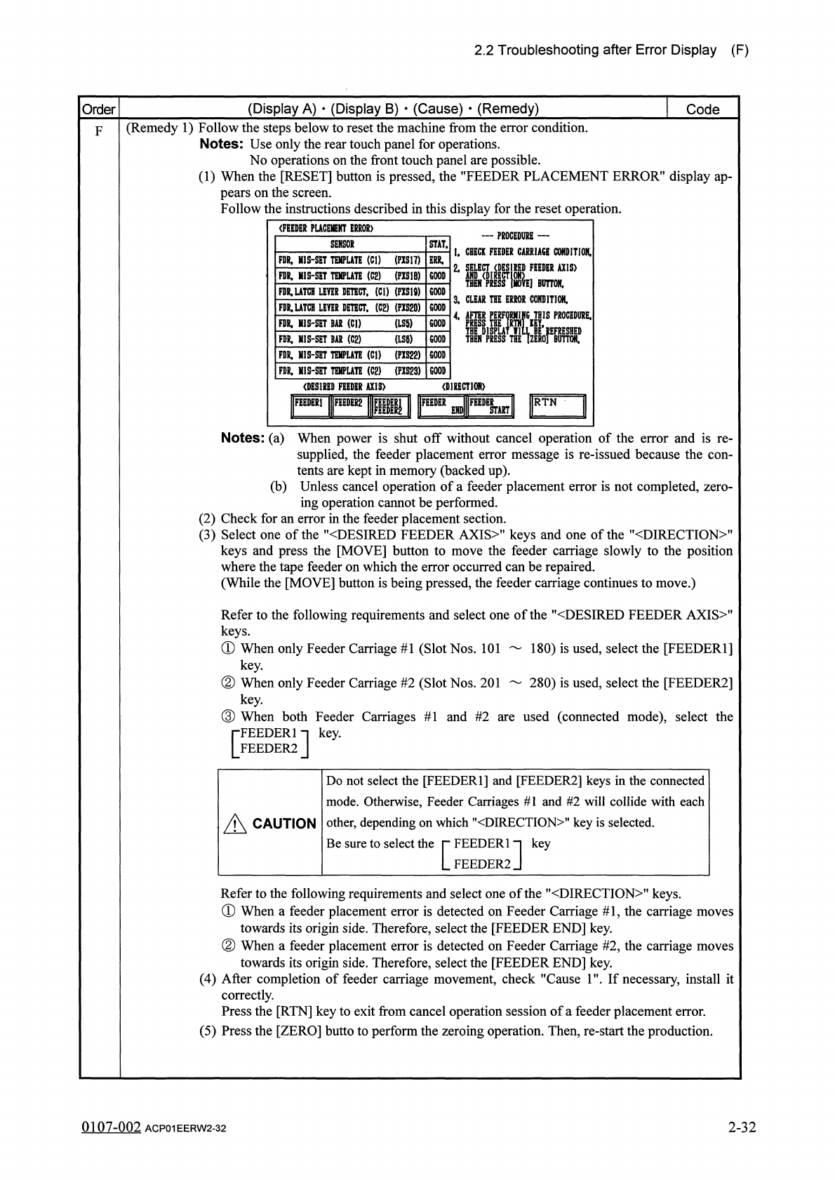
(
1
)
When
the
[
RESET
]
button
is
pressed
,
the
"
FEEDER
PLACEMENT
ERROR
”
display
ap
-
pears
on
the
screen
.
Follow
the
instructions
described
in
this
display
for
the
reset
operation
.
F
(
FEEDER
PUCEHENT
ERROR
)
一
PROCEDURE
—
I
.
CBECK
FEEDER
CARRIAGE
CONDITION
.
STAT
.
SENSOK
FDR
,
MIS
-
SET
TEMPLATE
(
Cl
)
(
PIS
17
)
2
.
®
IK
=
is
>
FDR
.
MIS
-
SET
TQIPUTE
(
C
2
)
(
PIS
1
B
)
COOP
10
M
FlIR
.
UTCHimRDETECT
,
(
Cl
)
(
PXS
18
)
3
»
CLEAR
THE
ERROR
CONDITION
.
THIS
PKOCEDURE
.
FDR
.
UTCB
LIVER
DETECT
,
(
C
2
) (
PXS
2
D
)
GOOD
il
THEN
}
(
LS
5
)
FDR
.
MIS
-
SET
BAR
(
Cl
)
GOOD
BAI
(
C
2
)
(
LSW
FR
MI
5
-
SCT
FDR
.
HIS
^
TEMPLATE
(
Cl
)
(
PXS
22
)
GOOD
GOOD
FDR
,
MIS
-
SET
TElffUTE
(
C
2
)
(
PIS
23
)
GOOD
(
DESIRED
FEEDER
AXIS
)
<
D
]
RECTI
0
N
>
I
圆
»
III
圓
2
|
g
|
I
II
瞧
Umll
IF
^
I
Notes
:
(
a
)
When
power
is
shut
off
without
cancel
operation
of
the
error
and
is
re
-
supplied
,
the
feeder
placement
error
message
is
re
-
issued
because
the
con
-
tents
are
kept
in
memory
(
backed
up
)
.
(
b
)
Unless
cancel
operation
of
a
feeder
placement
error
is
not
completed
,
zero
-
ing
operation
cannot
be
performed
.
(
2
)
Check
for
an
error
in
the
feeder
placement
section
.
(
3
)
Select
one
of
the
"
〈
DESIRED
FEEDER
AXIS
〉
"
keys
and
one
of
the
"
〈
DIRECTION
〉
"
keys
and
press
the
[
MOVE
]
button
to
move
the
feeder
carriage
slowly
to
the
position
where
the
tape
feeder
on
which
the
error
occurred
can
be
repaired
.
(
While
the
[
MOVE
]
button
is
being
pressed
,
the
feeder
carriage
continues
to
move
.
)
Refer
to
the
following
requirements
and
select
one
of
the
"
〈
DESIRED
FEEDER
AXIS
>
"
keys
.
①
When
only
Feeder
Carriage
#
1
(
Slot
Nos
.
101
180
)
is
used
,
select
the
[
FEEDER
1
]
key
.
②
When
only
Feeder
Carriage
#
2
(
Slot
Nos
.
201
280
)
is
used
,
select
the
[
FEEDER
2
]
key
.
③
When
both
Feeder
Carriages
#
1
and
#
2
are
used
(
connected
mode
)
,
select
the
FEEDER
1
FEEDER
2
key
.
[
]
Do
not
select
the
[
FEEDER
1
]
and
[
FEEDER
2
]
keys
in
the
connected
mode
.
Otherwise
,
Feeder
Carriages
#
1
and
#
2
will
collide
with
each
other
,
depending
on
which
"
DIRECTION
"
key
is
selected
.
Be
sure
to
select
A
CAUTION
the
rFEEDERln
LFEEDER
2
key
Refer
to
the
following
requirements
and
select
one
of
the
"
DIRECTION
"
keys
.
①
When
a
feeder
placement
error
is
detected
on
Feeder
Carriage
#
1
,
the
carriage
moves
towards
its
origin
side
.
Therefore
,
select
the
[
FEEDER
END
]
key
.
②
When
a
feeder
placement
error
is
detected
on
Feeder
Carriage
#
2
,
the
carriage
moves
towards
its
origin
side
.
Therefore
,
select
the
[
FEEDER
END
]
key
.
(
4
)
After
completion
of
feeder
carriage
movement
,
check
"
Cause
1
'
If
necessary
,
install
it
correctly
.
Press
the
[
RTN
]
key
to
exit
from
cancel
operation
session
of
a
feeder
placement
error
.
(
5
)
Press
the
[
ZERO
]
butto
to
perform
the
zeroing
operation
.
Then
,
re
-
start
the
production
.
0107
-
002
ACP
01
EERW
2
-
32
2
-
32
2.2
Troubleshooting
after
Error
Display
(
F
)
(
Display
A
)
•
(
Display
B
)
•
(
Cause
)
•
(
Remedy
)
Order
Code
(
Display
A
)
THE
FEEDER
INDEX
F
(
Display
B
)
THE
STRUCTURE
OF
FEEDER
INDEX
LEVER
#
2
WAS
NOT
ACTIVATED
.
;
PHS
36
64
-
03
-
01
LEVER
#
2
(
Cause
1
)
Dirt
adheres
to
the
sensor
.
(
Cause
2
)
An
error
may
have
occurred
in
the
tape
feeding
mechanism
.
The
sensor
is
defective
.
(
Remedy
1
)
Wipe
off
dirt
on
the
sensor
.
(
Remedy
2
)
Contact
our
service
personnel
for
details
.
(
Display
A
)
THE
FEEDER
INDEX
LEVER
#
2
(
Display
B
)
THE
FEEDER
INDEX
LEVER
#
2
MOVES
DE
-
64
-
03
-
02
SPITE
BEING
HELD
BY
STOPPER
.
(
Cause
1
)
When
the
optical
beam
of
the
sensor
was
set
in
the
"
E
/
R
,
f
condition
,
it
was
shielded
(
not
ceived
)
.
(
E
/
R
:
Light
Emitted
and
Received
)
.
re
-
(
Remedy
1
)
Press
the
[
RESET
]
button
to
cancel
the
error
and
check
if
the
optical
beam
of
the
sensor
is
set
in
the
nE
/
NR
”
or
the
,
fE
/
R
"
condition
.
(
E
/
NR
:
Light
Emitted
and
Not
Received
,
E
/
R
:
Light
Emitted
and
Received
)
Cover
the
optical
beam
of
the
sensor
with
a
piece
of
paper
to
check
the
condition
.
Ref
.
:
Never
detach
the
sensor
.
Otherwise
,
the
optical
axis
shifts
,
causing
the
timing
to
drift
.
Whenever
the
sensor
was
detached
,
consult
our
service
personnel
for
the
attachment
.
(
Display
A
)
THE
FEEDER
INDEX
LEVER
#
2
(
Display
B
)
THE
FEEDER
INDEX
LEVER
#
2
DOES
NOT
64
-
03
-
03
MOVE
EVEN
THOUGH
STOPPER
WAS
OPEN
.
(
Cause
1
)
When
the
optical
beam
of
the
sensor
was
set
in
the
"
E
/
NR
"
condition
,
it
was
received
.
(
E
/
NR
:
Light
Emitted
and
Not
Received
)
(
Remedy
1
)
Press
the
[
RESET
]
button
to
cancel
the
error
and
check
if
the
optical
beam
of
the
sensor
is
set
in
the
nE
/
NRM
or
the
”
E
/
R
”
condition
.
(
E
/
NR
:
Light
Emitted
and
Not
Received
,
E
/
R
:
Light
Emitted
and
Received
)
.
Cover
the
optical
beam
of
the
sensor
with
a
piece
of
paper
to
check
the
condition
.
Ref
.
:
Never
detach
the
sensor
.
Otherwise
,
the
optical
axis
shifts
,
causing
the
timing
to
drift
.
Whenever
the
sensor
was
detached
,
consult
our
service
personnel
for
the
attachment
.
99
in
-
nm
2
-
33
ACP
01
EERW
2
-
33
2.2
Troubleshooting
after
Error
Display
(
F
)
(
Display
A
)
•
(
Display
B
)
•
(
Causf
)
•
(
Remedy
)
Order
Code
(
Display
A
)
THE
FEEDER
ADHESIVE
TAPE
(
Display
B
)
THE
STRUCTURE
OF
FEEDER
ADHESIVE
F
64
-
04
-
01
TAPE
LEVER
WAS
NOT
ACTIVATED
,
;
PHS
37
(
Cause
1
)
An
error
was
found
in
the
adhesive
tape
take
-
up
mechanism
or
the
photosensor
(
PHS
37
)
.
(
Cause
2
)
Self
-
Diagnostics
Error
Message
(
Remedy
1
)
When
dirt
adheres
to
the
sensor
,
wipe
it
off
.
When
an
error
is
found
in
the
adhesive
tape
take
-
up
mechanism
,
consult
our
service
personnel
for
the
remedy
.
(
Remedy
2
)
Zero
all
devices
by
pressing
the
[
ZERO
]
button
and
then
re
-
start
the
operation
.
When
the
trouble
cannot
be
fixed
,
consult
our
service
personnel
for
the
remedy
.
(
Display
A
)
THE
FEEDER
ADHESIVE
TAPE
(
Display
B
)
THE
FEEDER
COVER
TAPE
LEVER
MOVES
64
-
04
-
02
DESPITE
BEING
HELD
BY
STOPPER
.
(
Cause
1
)
Even
though
the
stopper
was
turned
on
while
working
,
the
lever
moved
down
and
the
optical
shielded
(
not
received
)
.
beam
of
the
sensor
was
(
Remedy
1
)
Press
the
[
RESET
]
button
to
cancel
the
error
and
remove
the
cause
.
When
the
sensor
is
dirty
and
shielded
(
not
received
)
,
wipe
off
dirt
on
the
sensor
and
then
per
-
form
the
zeroing
operation
.
(
Display
A
)
THE
FEEDER
ADHESIVE
TAPE
(
Display
B
)
THE
FEEDER
ADHESIVE
TAPE
LEVER
DOES
NOT
MOVE
EVEN
THOUGH
STOPPER
WAS
64
-
04
-
03
OPEN
.
(
Cause
1
)
Although
the
stopper
was
turned
off
while
working
,
the
lever
did
not
move
down
and
the
opti
-
cal
beam
of
the
sensor
was
not
shielded
(
received
)
.
(
Remedy
1
)
Press
the
[
RESET
]
button
to
cancel
the
error
and
remove
the
cause
.
When
the
sensor
is
dirty
and
shielded
(
not
received
)
,
wipe
off
dirt
on
the
sensor
and
then
per
-
form
the
zeroing
operation
.
2
-
34
99
in
-
nm
ACP
01
EERW
2
-
34