5TROUBLESHOOTING_.pdf - 第53页
2.2 Troubleshooting after Error Display ( F ) ( Display A ) • ( Display B ) • ( Cause ) ■ ( Remedy ) Order Code ( Display A ) THE FEEDER INDEX LEVER # 1 F ( Display B ) THE FEEDER INDEX LEVER # 1 MOVES 64 - 06 - 02 DESPI…
2.2
Troubleshooting
after
Error
Display
(
F
)
(
Display
A
)
•
(
Display
B
)
*
(
Cause
)
*
(
Remedy
)
Code
Order
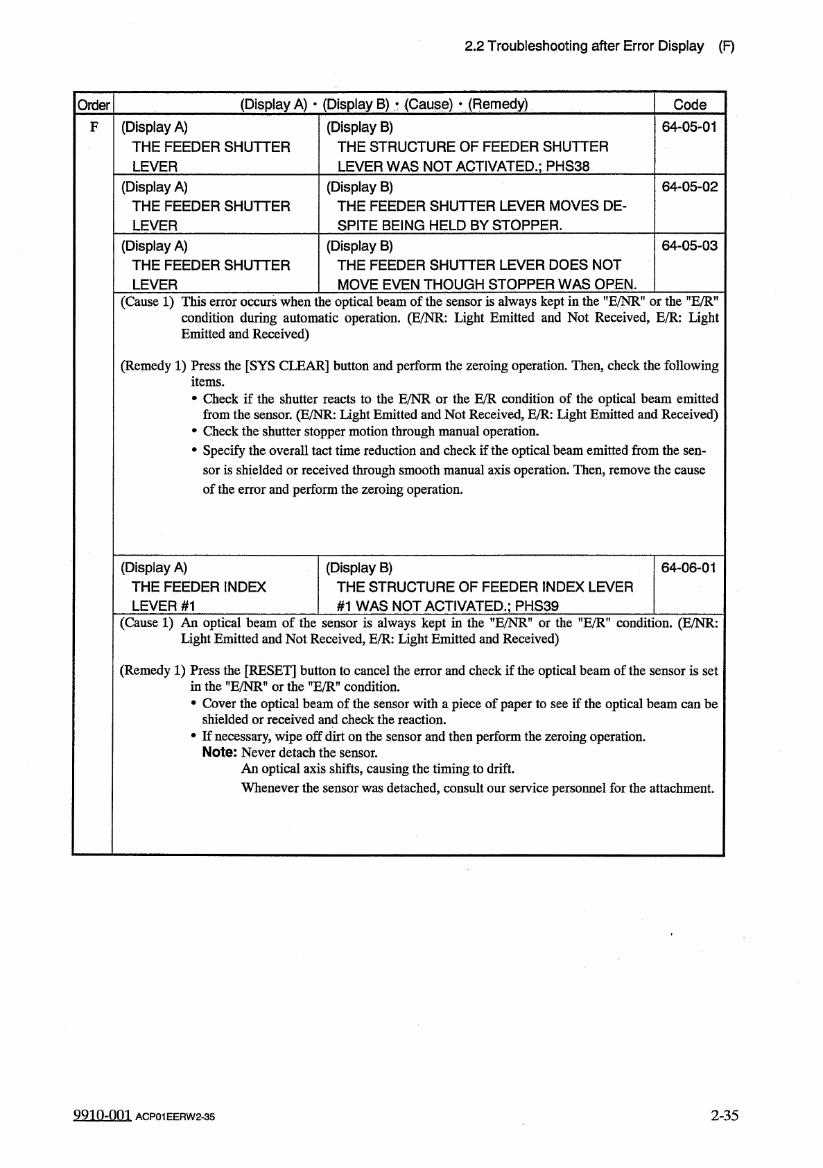
(
Display
A
)
THE
FEEDER
SHUTTER
LEVER
(
Display
B
)
THE
STRUCTURE
OF
FEEDER
SHUTTER
LEVER
WAS
NOT
ACTIVATED
.
;
PHS
38
64
-
05
-
01
F
(
Display
A
)
THE
FEEDER
SHUTTER
LEVER
(
Display
B
)
THE
FEEDER
SHUTTER
LEVER
MOVES
DE
-
SPITE
BEING
HELD
BY
STOPPER
.
64
-
05
-
02
(
Display
B
)
THE
FEEDER
SHUTTER
LEVER
DOES
NOT
(
Display
A
)
THE
FEEDER
SHUTTER
64
-
05
-
03
MOVE
EVEN
THOUGH
STOPPER
WAS
OPEN
.
LEVER
(
Cause
1
)
This
error
occurs
when
the
optical
beam
of
the
sensor
is
always
kept
in
the
uE
/
NRf
,
or
the
”
E
/
Rn
condition
during
automatic
operation
.
(
E
/
NR
:
Light
Emitted
and
Not
Received
,
E
/
R
:
Light
Emitted
and
Received
)
(
Remedy
1
)
Press
the
[
SYS
CLEAR
]
button
and
perform
the
zeroing
operation
.
Then
,
check
the
following
items
.
•
Check
if
the
shutter
reacts
to
the
E
/
NR
or
the
from
the
sensor
.
(
E
/
NR
:
Light
Emitted
and
Not
•
Check
the
shutter
stopper
motion
through
manual
operation
.
•
Specify
the
overall
tact
time
reduction
and
check
if
the
optical
beam
emitted
from
the
sen
-
sor
is
shielded
or
received
through
smooth
manual
axis
operation
.
Then
,
remove
the
cause
of
the
error
and
perform
the
zeroing
operation
.
condition
of
the
optical
beam
emitted
ed
,
E
/
R
:
Light
Emitted
and
Received
)
E
/
R
c
Receiv
(
Display
A
)
THE
FEEDER
INDEX
LEVER
#
1
(
Display
B
)
THE
STRUCTURE
OF
FEEDER
INDEX
LEVER
64
-
06
-
01
#
1
WAS
NOT
ACTIVATED
.
;
PHS
39
(
Cause
1
)
An
optical
beam
of
the
sensor
is
always
kept
in
the
"
E
/
NR
"
or
the
”
E
/
R
"
condition
.
(
E
/
NR
:
Light
Emitted
and
Not
Received
,
E
/
R
:
Light
Emitted
and
Received
)
(
Remedy
1
)
Press
the
[
RESET
]
button
to
cancel
the
error
and
check
if
the
optical
beam
of
the
sensor
is
set
in
the
"
E
/
NRM
or
the
”
E
/
R
”
condition
.
•
Cover
the
optical
beam
of
the
sensor
with
a
piece
of
paper
to
see
if
the
optical
beam
can
be
shielded
or
received
and
check
the
reaction
.
•
If
necessary
,
wipe
off
dirt
on
the
sensor
and
then
perform
the
zeroing
operation
.
Note
:
Never
detach
the
sensor
.
An
optical
axis
shifts
,
causing
the
timing
to
drift
.
Whenever
the
sensor
was
detached
,
consult
our
service
personnel
for
the
attachment
.
9910
-
001
2
-
35
ACP
01
EERW
2
-
35
2.2
Troubleshooting
after
Error
Display
(
F
)
(
Display
A
)
•
(
Display
B
)
•
(
Cause
)
■
(
Remedy
)
Order
Code
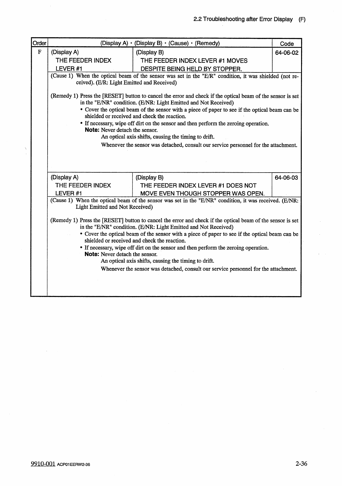
(
Display
A
)
THE
FEEDER
INDEX
LEVER
#
1
F
(
Display
B
)
THE
FEEDER
INDEX
LEVER
#
1
MOVES
64
-
06
-
02
DESPITE
BEING
HELD
BY
STOPPER
.
(
Cause
1
)
When
the
optical
beam
of
the
sensor
was
set
in
the
condition
,
it
was
shielded
(
not
ceived
)
.
(
E
/
R
:
Light
Emitted
and
Received
)
re
-
(
Remedy
1
)
Press
the
[
RESET
]
button
to
cancel
the
error
and
check
if
the
optical
beam
of
the
sensor
is
set
in
the
,
,
E
/
NR
,
f
condition
.
(
E
/
NR
:
Light
Emitted
and
Not
Received
)
•
Cover
the
optical
beam
of
the
sensor
with
a
piece
of
paper
to
see
if
the
optical
beam
can
be
shielded
or
received
and
check
the
reaction
.
•
If
necessary
,
wipe
off
dirt
on
the
sensor
and
then
perform
the
zeroing
operation
.
Note
:
Never
detach
die
sensor
.
An
optical
axis
shifts
,
causing
the
timing
to
drift
.
Whenever
the
sensor
was
detached
,
consult
our
service
personnel
for
the
attachment
.
(
Display
B
)
THE
FEEDER
INDEX
LEVER
#
1
DOES
NOT
(
Display
A
)
THE
FEEDER
INDEX
64
-
06
-
03
LEVER
#
1
MOVE
EVEN
THOUGH
STOPPER
WAS
OPEN
.
(
Cause
1
)
When
the
optical
beam
of
the
sensor
was
set
in
the
”
E
/
NR
"
condition
,
it
was
received
.
(
E
/
NR
:
Light
Emitted
and
Not
Received
)
(
Remedy
1
)
Press
the
[
RESET
]
button
to
cancel
the
error
and
check
if
the
optical
beam
of
the
sensor
is
set
in
the
,
?
E
/
NRf
,
condition
.
(
E
/
NR
:
Light
Emitted
and
Not
Received
)
•
Cover
the
optical
beam
of
the
sensor
with
a
piece
of
paper
to
see
if
the
optical
beam
can
be
shielded
or
received
and
check
the
reaction
.
•
If
necessary
,
wipe
off
dirt
on
the
sensor
and
then
perform
the
zeroing
operation
.
Note
:
Never
detach
the
sensor
.
An
optical
axis
shifts
,
causing
the
timing
to
drift
.
Whenever
the
sensor
was
detached
,
consult
our
service
personnel
for
the
attachment
.
9910
-
001
2
-
36
ACP
01
EERW
2
-
36
2.2
Troubleshooting
after
Error
Display
(
H
)
(
Display
A
)
•
(
Display
B
)
•
(
Caus
受
)
•
(
Remedy
)
Order
Code
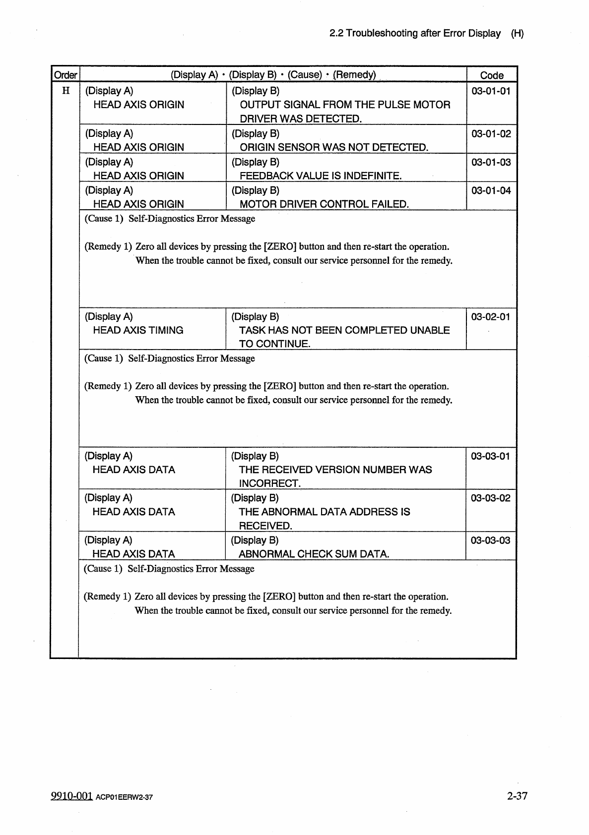
(
Display
A
)
HEAD
AXIS
ORIGIN
(
Display
B
)
OUTPUT
SIGNAL
FROM
THE
PULSE
MOTOR
DRIVER
WAS
DETECTED
.
H
03
-
01
-
01
(
Display
A
)
HEAD
AXIS
ORIGIN
(
Display
B
)
ORIGIN
SENSOR
WAS
NOT
DETECTED
.
03
-
01
-
02
(
Display
A
)
HEAD
AXIS
ORIGIN
(
Display
B
)
FEEDBACK
VALUE
IS
INDEFINITE
.
03
-
01
-
03
(
Display
A
)
HEAD
AXIS
ORIGIN
(
Display
B
)
MOTOR
DRIVER
CONTROL
FAILED
.
03
-
01
-
04
(
Cause
1
)
Self
-
Diagnostics
Error
Message
(
Remedy
1
)
Zero
all
devices
by
pressing
the
[
ZERO
]
button
and
then
re
-
start
the
operation
.
When
the
trouble
cannot
be
fixed
,
consult
our
service
personnel
for
the
remedy
.
(
Display
A
)
HEAD
AXIS
TIMING
(
Display
B
)
TASK
HAS
NOT
BEEN
COMPLETED
UNABLE
TO
CONTINUE
.
03
-
02
-
01
(
Cause
1
)
Self
-
Diagnostics
Error
Message
(
Remedy
1
)
Zero
all
devices
by
pressing
the
[
ZERO
]
button
and
then
re
-
start
the
operation
.
When
the
trouble
cannot
be
fixed
,
consult
our
service
personnel
for
the
remedy
.
(
Display
A
)
HEAD
AXIS
DATA
(
Display
B
)
THE
RECEIVED
VERSION
NUMBER
WAS
INCORRECT
.
03
-
03
-
01
(
Display
A
)
HEAD
AXIS
DATA
(
Display
B
)
THE
ABNORMAL
DATA
ADDRESS
IS
RECEIVED
.
03
-
03
-
02
(
Display
A
)
HEAD
AXIS
DATA
(
Display
B
)
ABNORMAL
CHECK
SUM
DATA
.
03
-
03
-
03
(
Cause
1
)
Self
-
Diagnostics
Error
Message
(
Remedy
1
)
Zero
all
devices
by
pressing
the
[
ZERO
]
button
and
then
re
-
start
the
operation
.
When
the
trouble
cannot
be
fixed
,
consult
our
service
personnel
for
the
remedy
.
9910
-
001
2
-
37
ACP
01
EERW
2
-
37