5TROUBLESHOOTING_.pdf - 第65页
2.2 Troubleshooting after Error Display ( N ) ( Display A ) • ( Display B ) • ( Cause ) • ( Remedy ) Order Code ( Display A ) NOZZLE POSITION ( Display B ) THE UNSELECTED NOZZLE WAS NOT STORED . ; PHS 20 63 - 02 - 04 N (…
2.2
Troubleshooting
after
Error
Display
(
M
)
(
Display
A
)
•
(
Display
B
)
•
(
Cause
)
•
(
Remedy
)
Order
Code
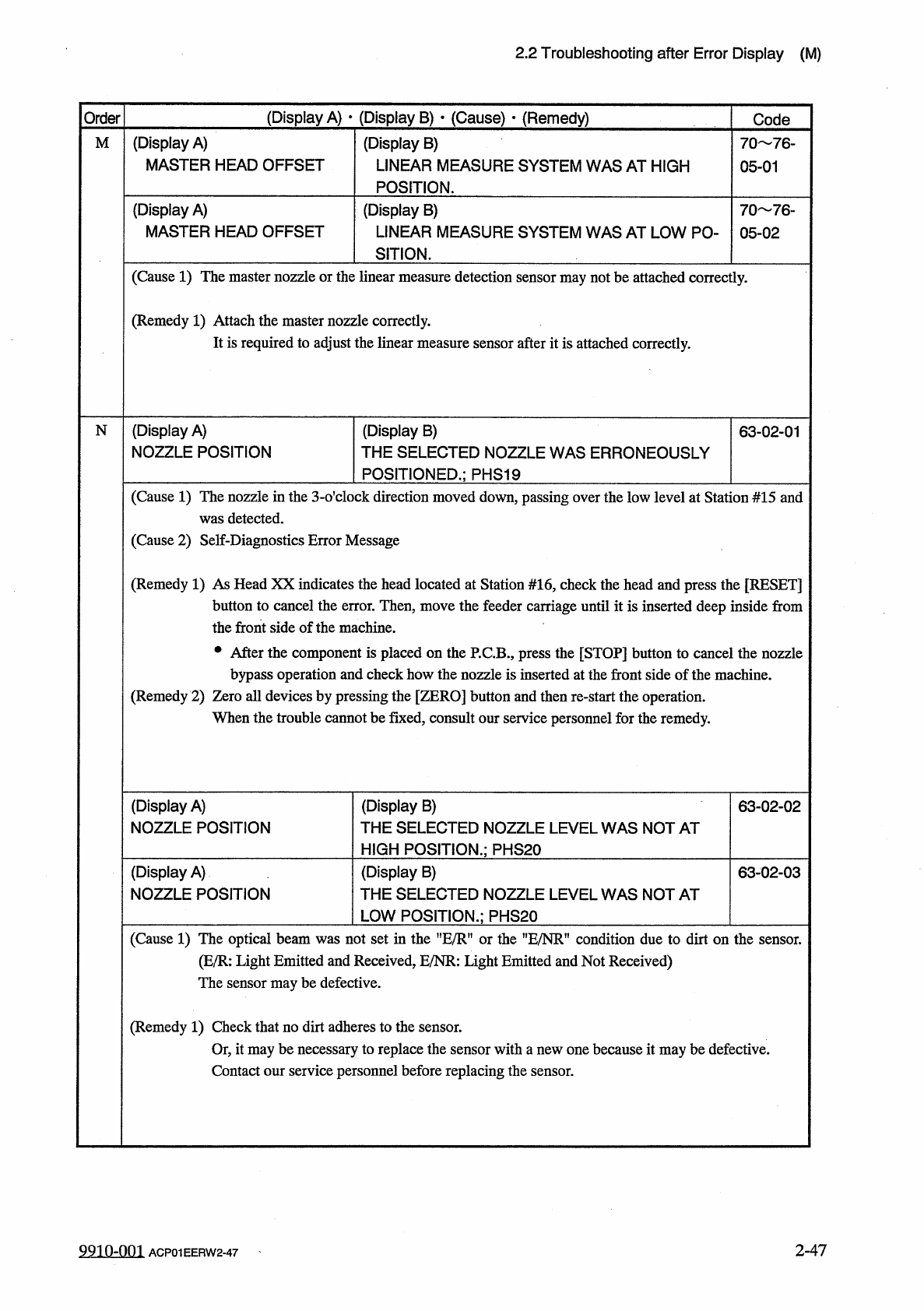
(
Display
A
)
MASTER
HEAD
OFFSET
(
Display
B
)
LINEAR
MEASURE
SYSTEM
WAS
AT
HIGH
POSITION
.
M
70
76
-
05
-
01
(
Display
A
)
MASTER
HEAD
OFFSET
(
Display
B
)
LINEAR
MEASURE
SYSTEM
WAS
AT
LOW
PO
-
SITION
.
70
76
_
05
-
02
(
Cause
1
)
The
master
nozzle
or
the
linear
measure
detection
sensor
may
not
be
attached
correctly
.
(
Remedy
1
)
Attach
the
master
nozzle
correctly
.
It
is
required
to
adjust
the
linear
measure
sensor
after
it
is
attached
correctly
.
(
Display
A
)
NOZZLE
POSITION
(
Display
B
)
THE
SELECTED
NOZZLE
WAS
ERRONEOUSLY
POSITIONED
.
;
PHS
19
N
63
-
02
-
01
(
Cause
1
)
The
nozzle
in
the
3
-
o
'
clock
direction
moved
down
,
passing
over
the
low
level
at
Station
#
15
and
was
detected
.
(
Cause
2
)
Self
-
Diagnostics
Error
Message
(
Remedy
1
)
As
Head
XX
indicates
the
head
located
at
Station
#
16
,
check
the
head
and
press
the
[
RESET
]
button
to
cancel
the
error
.
Then
,
move
the
feeder
carriage
until
it
is
inserted
deep
inside
from
the
front
side
of
the
machine
.
•
After
the
component
is
placed
on
the
P
.
C
.
B
.
,
press
the
[
STOP
]
button
to
cancel
the
nozzle
bypass
operation
and
check
how
the
nozzle
is
inserted
at
the
front
side
of
the
machine
.
(
Remedy
2
)
Zero
all
devices
by
pressing
the
[
ZERO
]
button
and
then
re
-
start
the
operation
.
When
the
trouble
cannot
be
fixed
,
consult
our
service
personnel
for
the
remedy
.
(
Display
B
)
THE
SELECTED
NOZZLE
LEVEL
WAS
NOT
AT
HIGH
POSITION
.
;
PHS
20
(
Display
A
)
NOZZLE
POSITION
63
-
02
-
02
(
Display
A
)
NOZZLE
POSITION
(
Display
B
)
THE
SELECTED
NOZZLE
LEVEL
WAS
NOT
AT
LOW
POSITION
.
;
PHS
20
63
-
02
-
03
(
Cause
1
)
The
optical
beam
was
not
set
in
the
nE
/
R
"
or
the
HE
/
NRn
condition
due
to
dirt
on
the
sensor
.
(
E
/
R
:
Light
Emitted
and
Received
,
E
/
NR
:
Light
Emitted
and
Not
Received
)
The
sensor
may
be
defective
.
(
Remedy
1
)
Check
that
no
dirt
adheres
to
the
sensor
.
Or
,
it
may
be
necessary
to
replace
the
sensor
with
a
new
one
because
it
may
be
defective
.
Contact
our
service
personnel
before
replacing
the
sensor
.
2
-
47
99
in
-
oni
ACP
01
EERW
2
-
47
2.2
Troubleshooting
after
Error
Display
(
N
)
(
Display
A
)
•
(
Display
B
)
•
(
Cause
)
•
(
Remedy
)
Order
Code
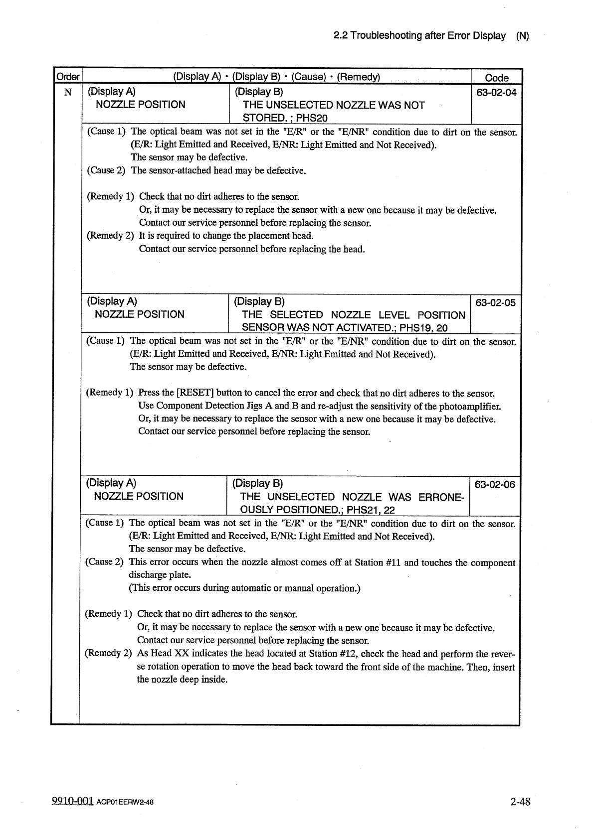
(
Display
A
)
NOZZLE
POSITION
(
Display
B
)
THE
UNSELECTED
NOZZLE
WAS
NOT
STORED
.
;
PHS
20
63
-
02
-
04
N
(
Cause
1
)
The
optical
beam
was
not
set
in
the
”
E
/
R
"
or
the
"
E
/
NR
”
condition
due
to
dirt
on
the
sensor
.
(
E
/
R
:
Light
Emitted
and
Received
,
E
/
NR
:
Light
Emitted
and
Not
Received
)
.
The
sensor
maybe
defective
.
(
Cause
2
)
The
sensor
-
attached
head
may
be
defective
.
(
Remedy
1
)
Check
that
no
dirt
adheres
to
the
sensor
.
Or
,
it
maybe
necessary
to
replace
the
sensor
with
a
new
one
because
it
maybe
defective
.
Contact
our
service
personnel
before
replacing
the
sensor
.
(
Remedy
2
)
It
is
required
to
change
the
placement
head
.
Contact
our
service
personnel
before
replacing
the
head
.
(
Display
A
)
NOZZLE
POSITION
(
Display
B
)
THE
SELECTED
NOZZLE
LEVEL
POSITION
SENSOR
WAS
NOT
ACTIVATED
.
;
PHS
19
,
20
63
-
02
-
05
(
Cause
1
)
The
optical
beam
was
not
set
in
the
"
E
/
R
"
or
the
”
E
/
NR
"
condition
due
to
dirt
on
the
sensor
.
Light
Emitted
and
Received
,
E
/
NR
:
Light
Emitted
and
Not
Received
)
,
ensor
may
be
defective
.
(
E
/
R
:
The
s
(
Remedy
1
)
Press
the
[
RESET
]
button
to
cancel
the
error
and
check
that
no
dirt
adheres
to
the
sensor
.
Use
Component
Detection
Jigs
A
and
B
and
re
-
adjust
the
sensitivity
of
the
photoamplifier
.
Or
,
it
maybe
necessary
to
replace
the
sensor
with
a
new
one
because
it
maybe
defective
.
Contact
our
service
personnel
before
replacing
the
sensor
.
(
Display
A
)
NOZZLE
POSITION
(
Display
B
)
THE
UNSELECTED
NOZZLE
WAS
ERRONE
-
OUSLY
POSITIONED
.
;
PHS
21
,
22
63
-
02
-
06
(
Cause
1
)
The
optical
beam
was
not
set
in
the
"
E
/
R
"
or
the
"
E
/
NR
”
condition
due
to
dirt
on
the
sensor
.
(
E
/
R
:
Light
Emitted
and
Received
,
E
/
NR
:
Light
Emitted
and
Not
Received
)
.
The
sensor
maybe
defective
.
(
Cause
2
)
This
error
occurs
when
the
nozzle
almost
comes
off
at
Station
#
11
and
touches
the
component
discharge
plate
.
(
This
error
occurs
during
automatic
or
manual
operation
.
)
(
Remedy
1
)
Check
that
no
dirt
adheres
to
the
sensor
.
Or
,
it
maybe
necessary
to
replace
the
sensor
with
a
new
one
because
it
maybe
defective
.
Contact
our
service
personnel
before
replacing
the
sensor
.
(
Remedy
2
)
As
Head
XX
indicates
the
head
located
at
Station
#
12
,
check
the
head
and
perform
the
rever
-
se
rotation
operation
to
move
the
head
back
toward
the
front
side
of
the
machine
.
Then
,
insert
the
nozzle
deep
inside
.
991
Q
-
Q
01
ACP
01
EERW
2
-
48
2
-
48
2.2
Troubleshooting
after
Error
Display
(
N
)
(
Display
A
)
•
(
Display
B
)
•
(
Cause
)
r
{
Remedy
)
Order
Code
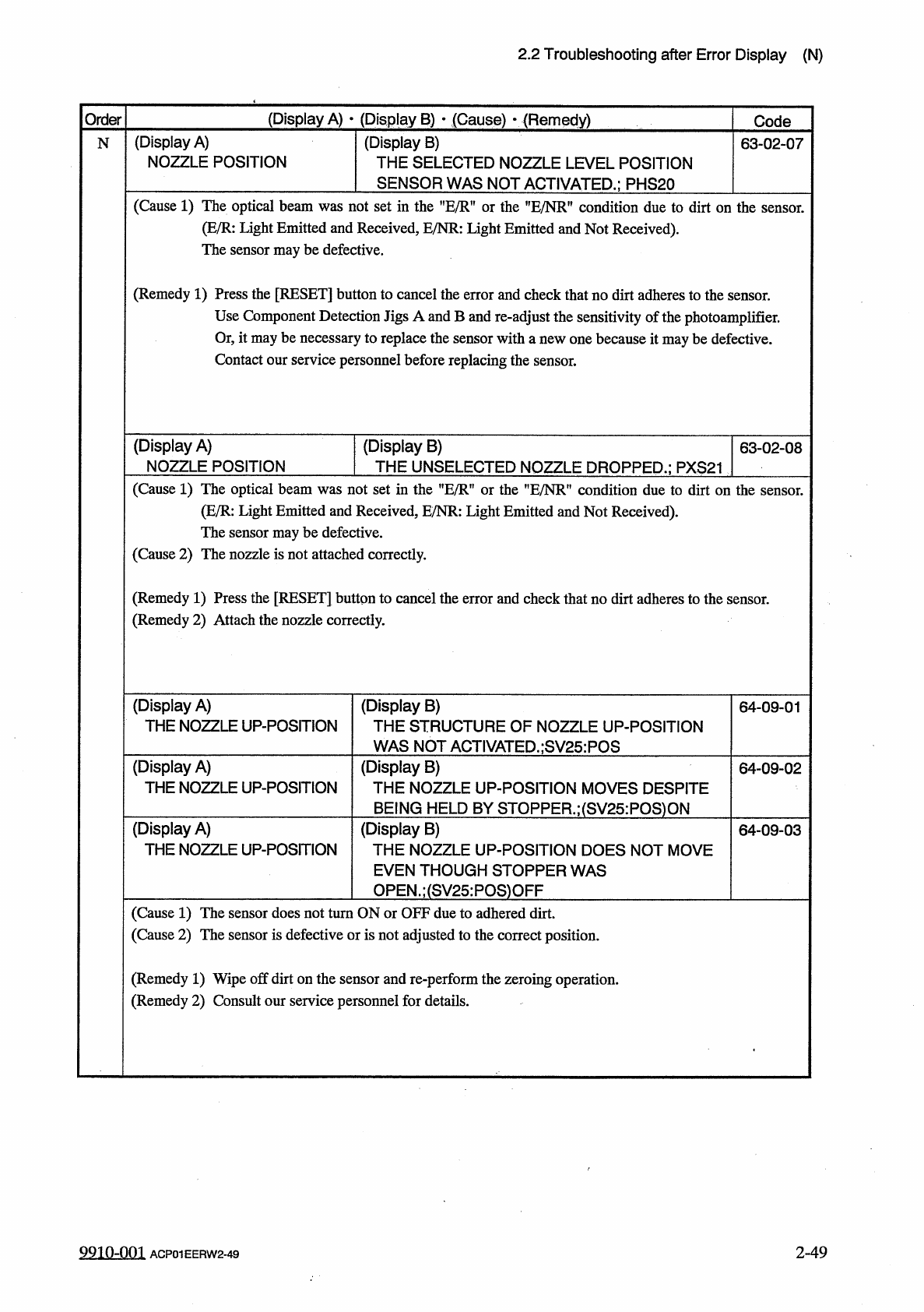
(
Display
A
)
NOZZLE
POSITION
(
Display
B
)
THE
SELECTED
NOZZLE
LEVEL
POSITION
SENSOR
WAS
NOT
ACTIVATED
.
;
PHS
20
N
63
-
02
-
07
(
Cause
1
)
The
optical
beam
was
not
set
m
the
,
fE
/
R
,
f
or
the
HE
/
NR
"
condition
due
to
dirt
on
the
sensor
.
(
E
/
R
:
Light
Emitted
and
Received
,
E
/
NR
:
Light
Emitted
and
Not
Received
)
.
The
sensor
may
be
defective
.
(
Remedy
1
)
Press
the
[
RESET
]
button
to
cancel
the
error
and
check
that
no
dirt
adheres
to
the
Use
Component
Detection
Jigs
A
and
B
and
re
-
adjust
the
sensitivity
of
the
photoamplifier
.
Or
,
it
may
be
necessary
to
replace
the
sensor
with
a
new
one
because
it
may
be
defective
.
Contact
our
service
personnel
before
replacing
the
sensor
.
sensor
.
(
Display
A
)
NOZZLE
POSITION
(
Display
B
)
THE
UNSELECTED
NOZZLE
DROPPED
.
;
PXS
21
63
-
02
-
08
(
Cause
1
)
The
optical
beam
was
not
set
in
the
"
E
/
R
"
or
the
”
E
/
NR
”
condition
due
to
dirt
on
the
sensor
.
(
E
/
R
:
Light
Emitted
and
Received
,
E
/
NR
:
Light
Emitted
and
Not
Received
)
.
The
sensor
may
be
defective
.
(
Cause
2
)
The
nozzle
is
not
attached
correctly
.
(
Remedy
1
)
Press
the
[
RESET
]
button
to
cancel
the
error
and
check
that
no
dirt
adheres
to
the
sensor
.
(
Remedy
2
)
Attach
the
nozzle
correctly
.
(
Display
A
)
THE
NOZZLE
UP
-
POSITION
(
Display
B
)
THE
STRUCTURE
OF
NOZZLE
UP
-
POSITION
WAS
NOT
ACTIVATED
.
;
SV
25
:
POS
64
-
09
-
01
(
Display
A
)
THE
NOZZLE
UP
-
POSITION
(
Display
B
)
THE
NOZZLE
UP
-
POSITION
MOVES
DESPITE
BEING
HELD
BY
STOPPER
.
;
(
SV
25
:
POS
)
ON
(
Display
B
)
THE
NOZZLE
UP
-
POSITION
DOES
NOT
MOVE
EVEN
THOUGH
STOPPER
WAS
OPEN
.
;
(
SV
25
:
POS
)
OFF
64
-
09
-
02
(
Display
A
)
THE
NOZZLE
UP
-
POSITION
64
-
09
-
03
(
Cause
1
)
The
sensor
does
not
turn
ON
or
OFF
due
to
adhered
dirt
.
(
Cause
2
)
The
sensor
is
defective
or
is
not
adjusted
to
the
correct
position
.
(
Remedy
1
)
Wipe
off
dirt
on
the
sensor
and
re
-
perform
the
zeroing
operation
.
(
Remedy
2
)
Consult
our
service
personnel
for
details
.
9910
-
001
2
-
49
ACP
01
EERW
2
-
49