5TROUBLESHOOTING_.pdf - 第71页
2.2 Troubleshooting after Error Display ( N ) ( Display A ) • ( Display B ) • ( Cause ) • ( Remedy ) Order Code ( Remedy 1 ) Follow the steps below to reset the machine to the normal condition . ( 1 ) When the [ RESET ] …
2.2
Troubleshooting
after
Error
Display
(
N
)
(
Display
A
)
•
(
Display
B
)
•
(
Cause
)
•
(
Remedy
)
Order
Code
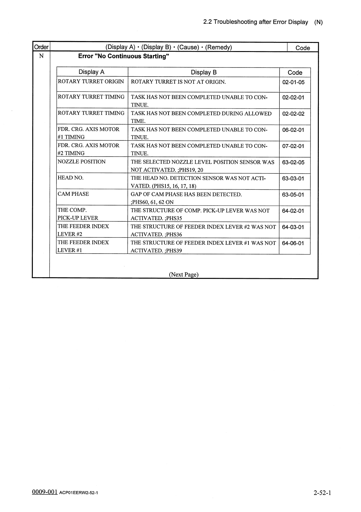
Error
"
No
Continuous
Starting
'
N
Display
A
Display
B
Code
ROTARY
TURRET
ORIGIN
ROTARY
TURRET
IS
NOT
AT
ORIGIN
.
02
-
01
-
05
ROTARY
TURRET
TIMING
TASK
HAS
NOT
BEEN
COMPLETED
UNABLE
TO
CON
-
TINUE
.
02
-
02
-
01
ROTARY
TURRET
TIMING
TASK
HAS
NOT
BEEN
COMPLETED
DURING
ALLOWED
TIME
.
02
-
02
-
02
FDR
.
CRG
.
AXIS
MOTOR
#
1
TIMING
TASK
HAS
NOT
BEEN
COMPLETED
UNABLE
TO
CON
-
TINUE
.
06
-
02
-
01
FDR
.
CRG
.
AXIS
MOTOR
#
2
TIMING
TASK
HAS
NOT
BEEN
COMPLETED
UNABLE
TO
CON
-
TINUE
.
07
-
02
-
01
NOZZLE
POSITION
THE
SELECTED
NOZZLE
LEVEL
POSITION
SENSOR
WAS
NOT
ACTIVATED
.
;
PHS
19
,
20
63
-
02
-
05
HEAD
NO
.
THE
HEAD
NO
.
DETECTION
SENSOR
WAS
NOT
ACTI
-
VATED
.
(
PHS
15
,
16
,
17
,
18
)
63
-
03
-
01
CAM
PHASE
GAP
OF
CAM
PHASE
HAS
BEEN
DETECTED
.
;
PHS
60
,
61
,
62
ON
63
-
05
-
01
THE
COMP
.
PICK
-
UP
LEVER
THE
STRUCTURE
OF
COMP
.
PICK
-
UP
LEVER
WAS
NOT
ACTIVATED
.
;
PHS
35
64
-
02
-
01
THE
FEEDER
INDEX
LEVER
#
2
THE
STRUCTURE
OF
FEEDER
INDEX
LEVER
#
2
WAS
NOT
ACTIVATED
.
;
PHS
36
64
-
03
-
01
THE
FEEDER
INDEX
LEVER
#
1
THE
STRUCTURE
OF
FEEDER
INDEX
LEVER
#
1
WAS
NOT
ACTIVATED
.
;
PHS
39
64
-
06
-
01
(
Next
Page
)
0009
-
001
2
-
52
-
1
ACP
01
EERW
2
-
52
-
1
2.2
Troubleshooting
after
Error
Display
(
N
)
(
Display
A
)
•
(
Display
B
)
•
(
Cause
)
•
(
Remedy
)
Order
Code
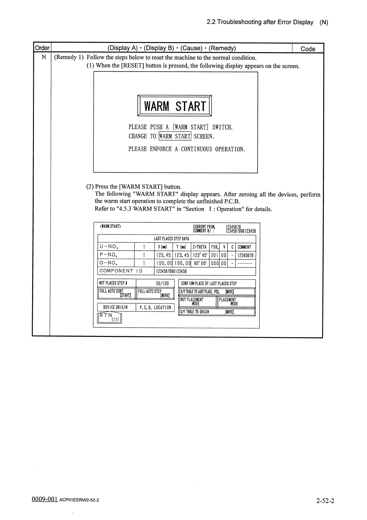
(
Remedy
1
)
Follow
the
steps
below
to
reset
the
machine
to
the
normal
condition
.
(
1
)
When
the
[
RESET
]
button
is
pressed
,
the
following
display
appears
on
the
screen
.
N
WARM
START
PLEASE
PUSH
A
[
WARM
START
]
SWITCH
.
CHANGE
TO
|
WARM
START
!
SCREEN
.
PLEASE
ENFORCE
A
CONTINUOUS
OPERATION
.
(
2
)
Press
the
[
WARM
START
]
button
.
The
following
"
WARM
START
"
display
appears
.
After
zeroing
all
the
devices
,
perform
the
warm
start
operation
to
complete
the
unfinished
P
.
C
.
B
.
Refer
to
"
4.5
.
3
WARM
START
”
in
"
Section
I
:
Operation
"
for
details
.
〈
WARM
START
〉
PRGM
,
1234567890123456
LAST
PLACED
STEP
DATA
X
(
n
)
U
-
NO
.
Y
(
in
)
Z
=
THETA
FDR
.
V
C
COMMENT
123
.
45
,
P
-
NO
。
123.45
123.45
201
12345678
O
-
NO
.
卯
•
00
,
100.00
100.00
000
00
COMPONENT
I
D
1234567890123456
NOT
PLACED
STEP
#
50
/
100
CONFIRM
PLACE
OF
LAST
PLACED
STEP
FULL
AUTO
C
0
NT
FULL
AUTO
STEP
X
/
Y
TABLE
TO
LAST
PUCE
,
POS
,
[
HOVE
]
(
START
)
[
MOVE
]
NOT
PLACEMENT
PLACEMENT
MODE
MODE
DEVICE
ORIGIN
P
.
C
.
B
.
LOCATION
[
MOVE
]
X
/
Y
TABLE
TO
ORIGIN
RTN
mi
0009
-
001
2
-
52
-
2
ACP
01
EERW
2
-
52
-
2
2.2
Troubleshooting
after
Error
Display
(
O
)
(
Display
A
)
•
(
Display
B
)
•
(
Cause
)
•
(
Remedy
)
Order
Code
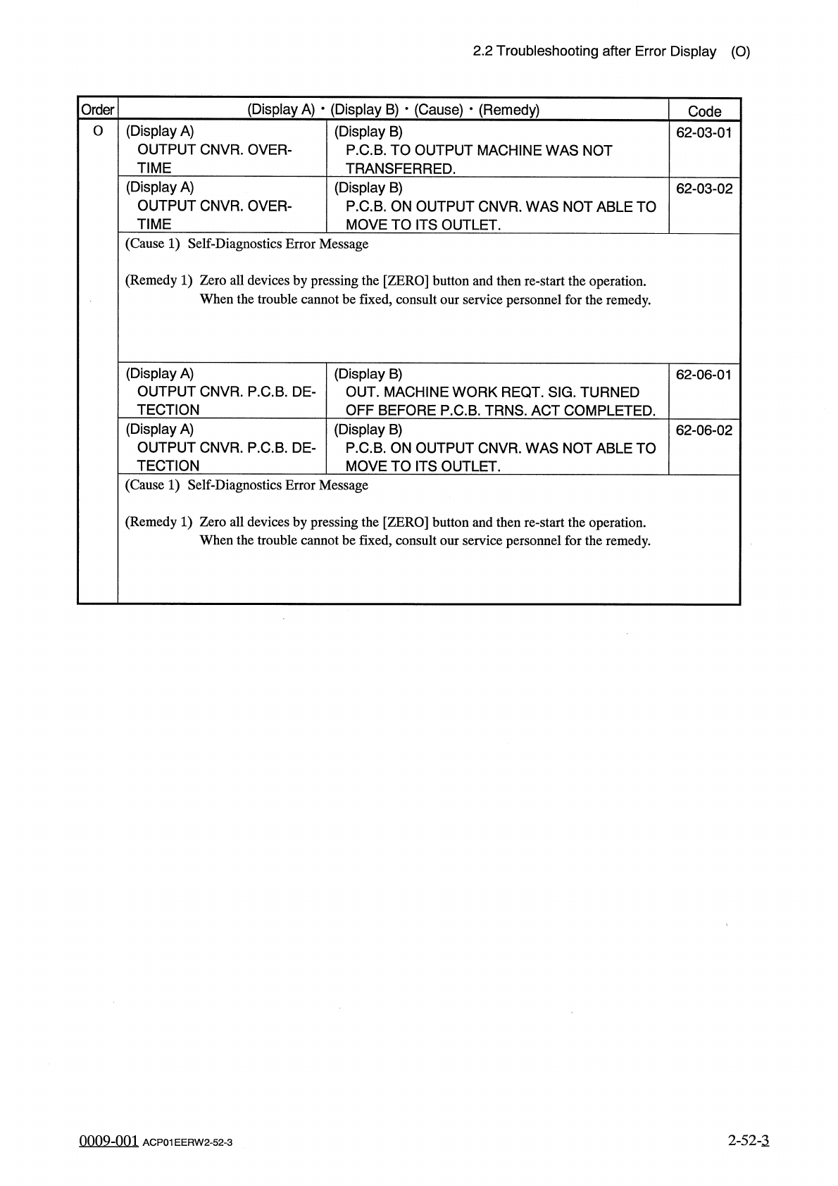
(
Display
A
)
OUTPUT
CNVR
.
OVER
-
TIME
O
(
Display
B
)
P
.
C
.
B
.
TO
OUTPUT
MACHINE
WAS
NOT
TRANSFERRED
.
62
-
03
-
01
(
Display
A
)
OUTPUT
CNVR
.
OVER
-
TIME
(
Display
B
)
P
.
C
.
B
.
ON
OUTPUT
CNVR
.
WAS
NOT
ABLE
TO
MOVE
TO
ITS
OUTLET
.
62
-
03
-
02
(
Cause
1
)
Self
-
Diagnostics
Error
Message
(
Remedy
1
)
Zero
all
devices
by
pressing
the
[
ZERO
]
button
and
then
re
-
start
the
operation
.
When
the
trouble
cannot
be
fixed
,
consult
our
service
personnel
for
the
remedy
.
(
Display
A
)
OUTPUT
CNVR
.
P
.
C
.
B
.
DE
-
TECTION
(
Display
B
)
OUT
.
MACHINE
WORK
REQT
.
SIG
.
TURNED
OFF
BEFORE
P
.
C
.
B
.
TRNS
.
ACT
COMPLETED
.
62
-
06
-
01
(
Display
A
)
OUTPUT
CNVR
.
P
.
C
.
B
.
DE
-
TECTION
(
Display
B
)
P
.
C
.
B
.
ON
OUTPUT
CNVR
.
WAS
NOT
ABLE
TO
MOVE
TO
ITS
OUTLET
.
62
-
06
-
02
(
Cause
1
)
Self
-
Diagnostics
Error
Message
(
Remedy
1
)
Zero
all
devices
by
pressing
the
[
ZERO
]
button
and
then
re
-
start
the
operation
.
When
the
trouble
cannot
be
fixed
,
consult
our
service
personnel
for
the
remedy
.
2
-
52
-
3
0009
-
001
ACP
01
EERW
2
-
52
-
3