5TROUBLESHOOTING_.pdf - 第74页
2.2 Troubleshooting after Error Display ( R ) ( Display A ) • ( Display B ) • ( Causa ) - ( Remedy ) Order Code ( Display A ) ROTARY TURRET ORIGIN ( Display B ) ROTARY TURRET ANGLE IS NOT AT ORIGIN . R 02 - 01 - 01 ( Dis…
2.2
Troubleshooting
after
Error
Display
(
P
)
(
Display
A
)
•
(
Display
B
)
•
(
Cause
)
•
(
Remedy
)
Order
Code
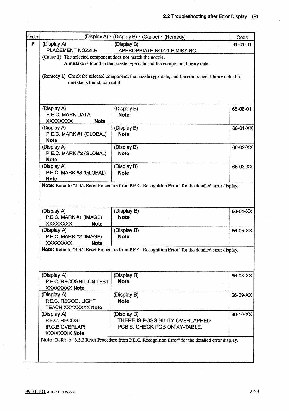
(
Display
A
)
PLACEMENT
NOZZLE
P
(
Display
B
)
APPROPRIATE
NOZZLE
MISSING
.
61
-
01
-
01
(
Cause
1
)
The
selected
component
does
not
match
the
nozzle
.
A
mistake
is
found
in
the
nozzle
type
data
and
the
component
library
data
.
(
Remedy
1
)
Check
the
selected
component
,
the
nozzle
type
data
,
and
the
component
library
data
.
If
a
mistake
is
found
,
correct
it
.
(
Display
A
)
P
.
E
.
C
.
MARK
DATA
XXXXXXXX
(
Display
B
)
Note
65
-
06
-
01
Note
(
Display
A
)
P
.
E
.
C
.
MARK
#
1
(
GLOBAL
)
Note
(
Display
B
)
Note
66
-
01
-
XX
(
Display
A
)
P
.
E
.
C
.
MARK
#
2
(
GLOBAL
)
Note
(
Display
B
)
Note
66
-
02
-
XX
(
Display
A
)
P
.
E
.
C
.
MARK
#
3
(
GLOBAL
)
Note
(
Display
B
)
66
-
03
-
XX
Note
Note
:
Refer
to
”
3.3
.
2
Reset
Procedure
from
P
.
E
.
C
.
Recognition
Error
"
for
the
detailed
display
.
error
(
Display
B
)
Note
(
Display
A
)
P
.
E
.
C
.
MARK
#
1
(
IMAGE
)
XXXXXXXX
66
-
04
-
XX
Note
(
Display
A
)
P
.
E
.
C
.
MARK
#
2
(
IMAGE
)
XXXXXXXX
(
Display
B
)
Note
66
-
05
-
XX
Note
Note
:
Refer
to
"
3.3
.
2
Reset
Procedure
from
P
.
E
.
C
.
Recognition
Error
'
1
for
the
detailed
error
display
.
(
Display
A
)
P
.
E
.
C
.
RECOGNITION
TEST
XXXXXXXX
Note
(
Display
B
)
Note
66
-
08
-
XX
(
Display
A
)
P
.
E
.
C
.
RECOG
.
LIGHT
TEACH
XXXXXXXX
Note
(
Display
B
)
Note
66
-
09
-
XX
(
Display
A
)
P
.
E
.
C
.
RECOG
.
(
P
.
C
.
B
.
OVERLAP
)
XXXXXXXX
Note
(
Display
B
)
THERE
IS
POSSIBILITY
OVERLAPPED
PCB
’
S
.
CHECK
PCB
ON
XY
-
TABLE
.
66
-
10
-
XX
Note
:
Refer
to
"
3.3
.
2
Reset
Procedure
from
P
.
E
.
C
.
Recognition
Error
"
for
the
detailed
error
display
.
99
in
-
nm
2
-
53
ACP
01
EERW
2
-
53
2.2
Troubleshooting
after
Error
Display
(
R
)
(
Display
A
)
•
(
Display
B
)
•
(
Causa
)
-
(
Remedy
)
Order
Code
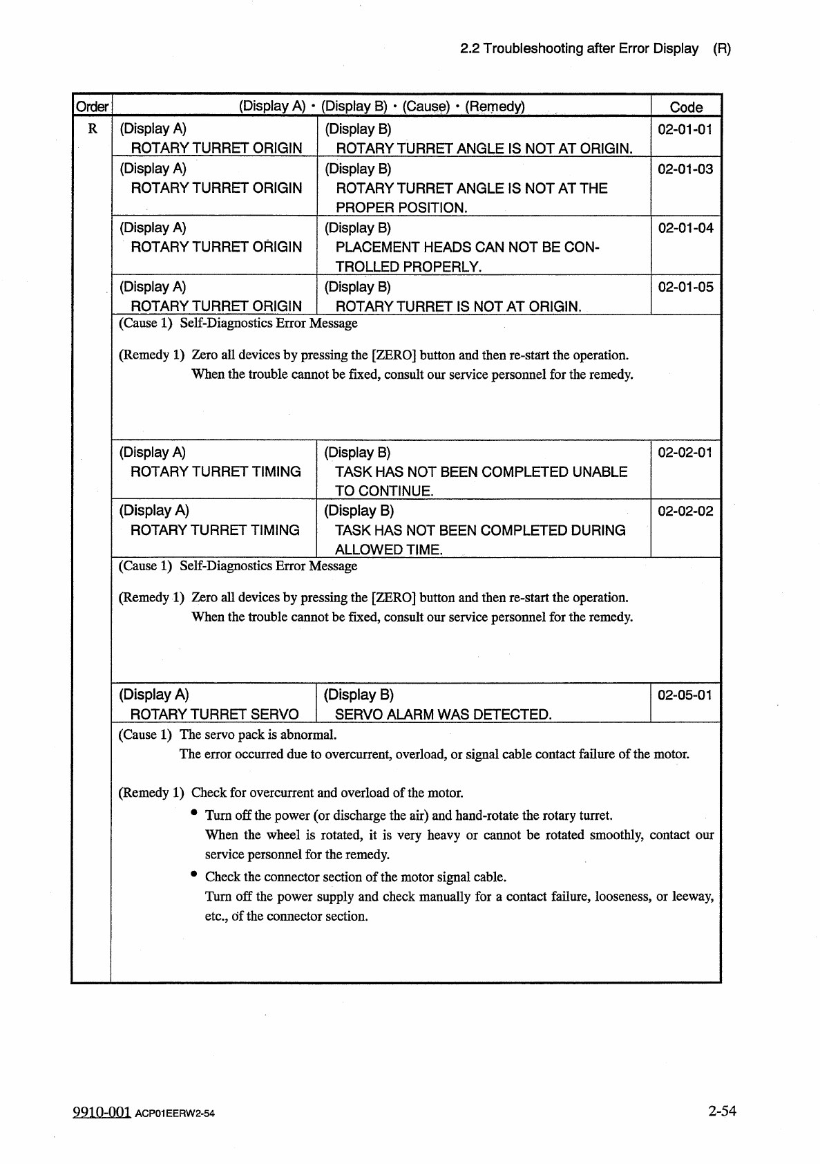
(
Display
A
)
ROTARY
TURRET
ORIGIN
(
Display
B
)
ROTARY
TURRET
ANGLE
IS
NOT
AT
ORIGIN
.
R
02
-
01
-
01
(
Display
A
)
ROTARY
TURRET
ORIGIN
(
Display
B
)
ROTARY
TURRET
ANGLE
IS
NOT
AT
THE
PROPER
POSITION
.
02
-
01
-
03
(
Display
A
)
ROTARY
TURRET
ORIGIN
(
Display
B
)
PLACEMENT
HEADS
CAN
NOT
BE
CON
-
TROLLED
PROPERLY
.
02
-
01
-
04
(
Display
A
)
ROTARY
TURRET
ORIGIN
(
Display
B
)
ROTARY
TURRET
IS
NOT
AT
ORIGIN
.
02
-
01
-
05
(
Cause
1
)
Self
-
Diagnostics
Error
Message
(
Remedy
1
)
Zero
all
devices
by
pressing
the
[
ZERO
]
button
and
then
re
-
stairt
the
operation
.
When
the
trouble
cannot
be
fixed
,
consult
our
service
personnel
for
the
remedy
.
(
Display
A
)
ROTARY
TURRET
TIMING
(
Display
B
)
TASK
HAS
NOT
BEEN
COMPLETED
UNABLE
TO
CONTINUE
.
02
-
02
-
01
(
Display
A
)
ROTARY
TURRET
TIMING
(
Display
B
)
TASK
HAS
NOT
BEEN
COMPLETED
DURING
02
-
02
-
02
ALLOWED
TIME
.
(
Cause
1
)
Self
-
Diagnostics
Error
Message
(
Remedy
1
)
Zero
all
devices
by
pressing
the
[
ZERO
]
button
and
then
re
-
start
the
operation
.
When
the
trouble
cannot
be
fixed
,
consult
our
service
personnel
for
the
remedy
.
(
Display
A
)
ROTARY
TURRET
SERVO
(
Display
B
)
SERVO
ALARM
WAS
DETECTED
.
02
-
05
-
01
(
Cause
1
)
The
servo
pack
is
abnormal
.
The
error
occurred
due
to
overcurrent
,
overload
,
or
signal
cable
contact
failure
of
the
motor
.
(
Remedy
1
)
Check
for
overcurrent
and
overload
of
the
motor
.
•
Turn
off
the
power
(
or
discharge
the
air
)
and
hand
-
rotate
the
rotary
turret
.
When
the
wheel
is
rotated
,
it
is
very
heavy
or
cannot
be
rotated
smoothly
,
contact
our
service
personnel
for
the
remedy
.
•
Check
the
connector
section
of
the
motor
signal
cable
.
Turn
off
the
power
supply
and
check
manually
for
a
contact
failure
,
looseness
,
or
leeway
,
etc
.
,
of
the
connector
section
.
2
-
54
9910
-
001
ACP
01
EERW
2
-
54
2.2
Troubleshooting
after
Error
Display
(
R
)
(
Display
A
)
•
(
Display
B
)
»
(
Cause
)
•
(
Remedy
)
Order
Code
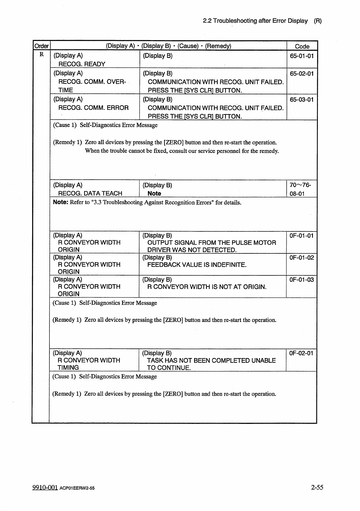
R
(
Display
A
)
RECOG
.
READY
(
Display
B
)
65
-
01
-
01
(
Display
A
)
RECOG
.
COMM
.
OVER
-
TIME
(
Display
B
)
COMMUNICATION
WITH
RECOG
.
UNIT
FAILED
.
PRESS
THE
[
SYS
CLR
1
BUTTON
,
65
-
02
-
01
(
Display
A
)
RECOG
.
COMM
.
ERROR
(
Display
B
)
COMMUNICATION
WITH
RECOG
.
UNIT
FAILED
.
PRESS
THE
「
SYS
CLR
1
BUTTON
.
65
-
03
-
01
(
Cause
1
)
Self
-
Diagnostics
Error
Message
(
Remedy
1
)
Zero
all
devices
by
pressing
the
[
ZERO
]
button
and
then
re
-
start
the
operation
.
When
the
trouble
cannot
be
fixed
,
consult
our
service
personnel
for
the
remedy
.
(
Display
A
)
RECOG
.
DATA
TEACH
(
Display
B
)
Note
70
76
-
08
-
01
Note
:
Refer
to
”
3.3
Troubleshooting
Against
Recognition
Errors
”
for
details
.
(
Display
A
)
R
CONVEYOR
WIDTH
ORIGIN
(
Display
B
)
OUTPUT
SIGNAL
FROM
THE
PULSE
MOTOR
DRIVER
WAS
NOT
DETECTED
.
0
F
-
01
-
01
(
Display
A
)
R
CONVEYOR
WIDTH
ORIGIN
(
Display
B
)
FEEDBACK
VALUE
IS
INDEFINITE
.
0
F
-
01
-
02
(
Display
A
)
R
CONVEYOR
WIDTH
ORIGIN
(
Display
B
)
R
CONVEYOR
WIDTH
IS
NOT
AT
ORIGIN
.
0
F
-
01
-
03
(
Cause
1
)
Self
-
Diagnostics
Error
Message
(
Remedy
1
)
Zero
all
devices
by
pressing
the
[
ZERO
]
button
and
then
re
-
start
the
operation
.
(
Display
A
)
R
CONVEYOR
WIDTH
TIMING
(
Display
B
)
TASK
HAS
NOT
BEEN
COMPLETED
UNABLE
TO
CONTINUE
.
0
F
-
02
-
01
(
Cause
1
)
Self
-
Diagnostics
Error
Message
(
Remedy
1
)
Zero
all
devices
by
pressing
the
[
ZERO
]
button
and
then
re
-
start
the
operation
.
9910
-
001
2
-
55
ACP
01
EERW
2
-
55