5TROUBLESHOOTING_.pdf - 第81页
2.2 Troubleshooting after Error Display ( T ) Order ( Display A ) • ( Display B ) • ( Cause ) * ( Remedy ) Code T ( Display A ) TRANSFER ORIGIN ( Display B ) OUTPUT SIGNAL FROM THE PULSE MOTOR DRIVER WAS NOT DETECTED . 0…
2.2
Troubleshooting
after
Error
Display
(
T
)
(
Display
A
)
•
(
Display
B
)
»
(
Cause
)
•
(
Remedy
)
Order
Code
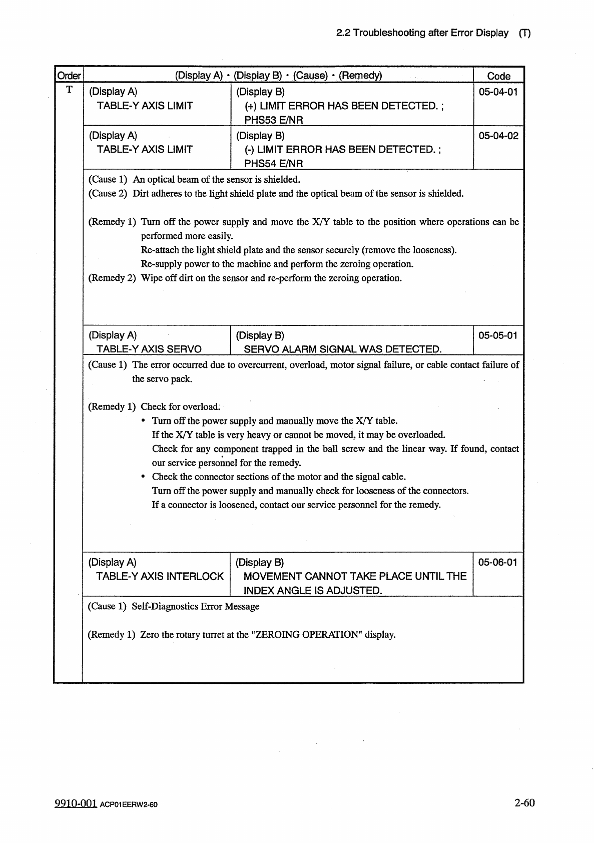
T
(
Display
A
)
TABLE
-
YAXIS
LIMIT
(
Display
B
)
(
+
)
LIMIT
ERROR
HAS
BEEN
DETECTED
.
:
PHS
53
E
/
NR
05
-
04
-
01
(
Display
A
)
TABLE
-
YAXIS
LIMIT
(
Display
B
)
(
-
)
LIMIT
ERROR
HAS
BEEN
DETECTED
.
;
PHS
54
E
/
NR
05
-
04
-
02
(
Cause
1
)
An
optical
beam
of
the
sensor
is
shielded
.
(
Cause
2
)
Dirt
adheres
to
the
light
shield
plate
and
the
optical
beam
of
the
sensor
is
shielded
.
(
Remedy
1
)
Turn
off
the
power
supply
and
move
the
X
/
Y
table
to
the
position
where
operations
can
be
performed
more
easily
.
the
light
shield
plate
and
the
sensor
securely
(
remove
the
looseness
)
,
power
to
the
machine
and
perform
the
zeroing
operation
.
(
Remedy
2
)
Wipe
off
dirt
on
the
sensor
and
re
-
perform
the
zeroing
operation
.
attach
i
supply
(
Display
A
)
TABLE
-
YAXIS
SERVO
(
Display
B
)
SERVO
ALARM
SIGNAL
WAS
DETECTED
.
05
-
05
-
01
(
Cause
1
)
The
error
occurred
due
to
overcurrent
,
overload
,
motor
signal
failure
,
or
cable
contact
failure
of
the
servo
pack
.
(
Remedy
1
)
Check
for
overload
.
•
Turn
off
the
power
supply
and
manually
move
the
X
/
Y
table
.
If
the
X
/
Y
table
is
very
heavy
or
cannot
be
moved
,
it
maybe
overloaded
.
Check
for
any
component
trapped
in
the
ball
screw
and
the
linear
way
.
If
found
,
contact
our
service
personnel
for
the
remedy
.
•
Check
the
connector
sections
of
the
motor
and
the
signal
cable
.
Turn
off
the
power
supply
and
manually
check
for
looseness
of
the
connectors
.
If
a
connector
is
loosened
,
contact
our
service
personnel
for
the
remedy
.
(
Display
A
)
TABLE
-
YAXIS
INTERLOCK
(
Display
B
)
MOVEMENT
CANNOT
TAKE
PLACE
UNTIL
THE
INDEX
ANGLE
IS
ADJUSTED
.
05
-
06
-
01
(
Cause
1
)
Self
-
Diagnostics
Error
Message
(
Remedy
1
)
Zero
the
rotary
turret
at
the
"
ZEROING
OPERATION
'
1
display
.
2
-
60
9910
-
001
ACP
01
EERW
2
-
60
2.2
Troubleshooting
after
Error
Display
(
T
)
Order
(
Display
A
)
•
(
Display
B
)
•
(
Cause
)
*
(
Remedy
)
Code
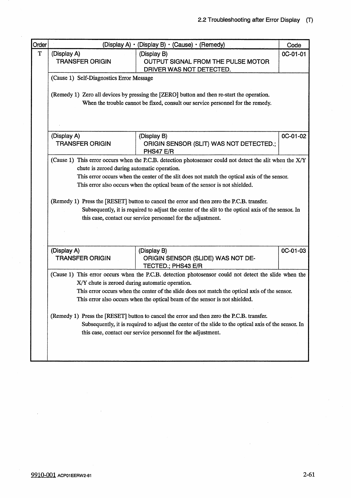
T
(
Display
A
)
TRANSFER
ORIGIN
(
Display
B
)
OUTPUT
SIGNAL
FROM
THE
PULSE
MOTOR
DRIVER
WAS
NOT
DETECTED
.
0
C
-
01
-
01
(
Cause
1
)
Self
-
Diagnostics
Error
Message
(
Remedy
1
)
Zero
all
devices
by
pressing
the
[
ZERO
]
button
and
then
re
-
start
the
operation
.
When
the
trouble
cannot
be
fixed
,
consult
our
service
personnel
for
the
remedy
.
(
Display
A
)
TRANSFER
ORIGIN
0
C
-
01
-
02
(
Display
B
)
ORIGIN
SENSOR
(
SLIT
)
WAS
NOT
DETECTED
.
;
PHS
47
E
/
R
(
Cause
1
)
This
error
occurs
when
the
P
.
C
.
B
.
detection
photosensor
could
not
detect
the
slit
when
the
X
/
Y
chute
is
zeroed
during
automatic
operation
.
This
error
occurs
when
the
center
of
the
slit
does
not
match
the
optical
axis
of
the
sensor
.
This
error
also
occurs
when
the
optical
beam
of
the
sensor
is
not
shielded
.
(
Remedy
1
)
Press
the
[
RESET
]
button
to
cancel
the
error
and
then
zero
the
P
.
C
.
B
.
transfer
.
Subsequently
,
it
is
required
to
adjust
the
center
of
the
slit
to
the
optical
axis
of
the
sensor
.
In
this
case
,
contact
our
service
personnel
for
the
adjustment
.
(
Display
A
)
TRANSFER
ORIGIN
(
Display
B
)
ORIGIN
SENSOR
(
SLIDE
)
WAS
NOT
DE
-
TECTED
.
;
PHS
43
E
/
R
0
C
-
01
-
03
(
Cause
1
)
This
error
occurs
when
the
P
.
C
.
B
.
detection
photosensor
could
not
detect
the
slide
when
the
X
/
Y
chute
is
zeroed
during
automatic
operation
.
This
error
occurs
when
the
center
of
the
slide
does
not
match
the
optical
axis
of
the
sensor
.
This
error
also
occurs
when
the
optical
beam
of
the
sensor
is
not
shielded
.
(
Remedy
1
)
Press
the
[
RESET
]
button
to
cancel
the
error
and
then
zero
the
P
.
C
.
B
.
transfer
.
Subsequently
,
it
is
required
to
adjust
the
center
of
the
slide
to
the
optical
axis
of
the
sensor
.
In
this
case
,
contact
our
service
personnel
for
the
adjustment
.
2
-
61
9910
-
001
ACP
01
EERW
2
-
61
2.2
Troubleshooting
after
Error
Display
(
T
)
(
Display
A
)
•
(
Display
B
)
■
(
Gauge
)
•
(
Remedy
)
Order
Code
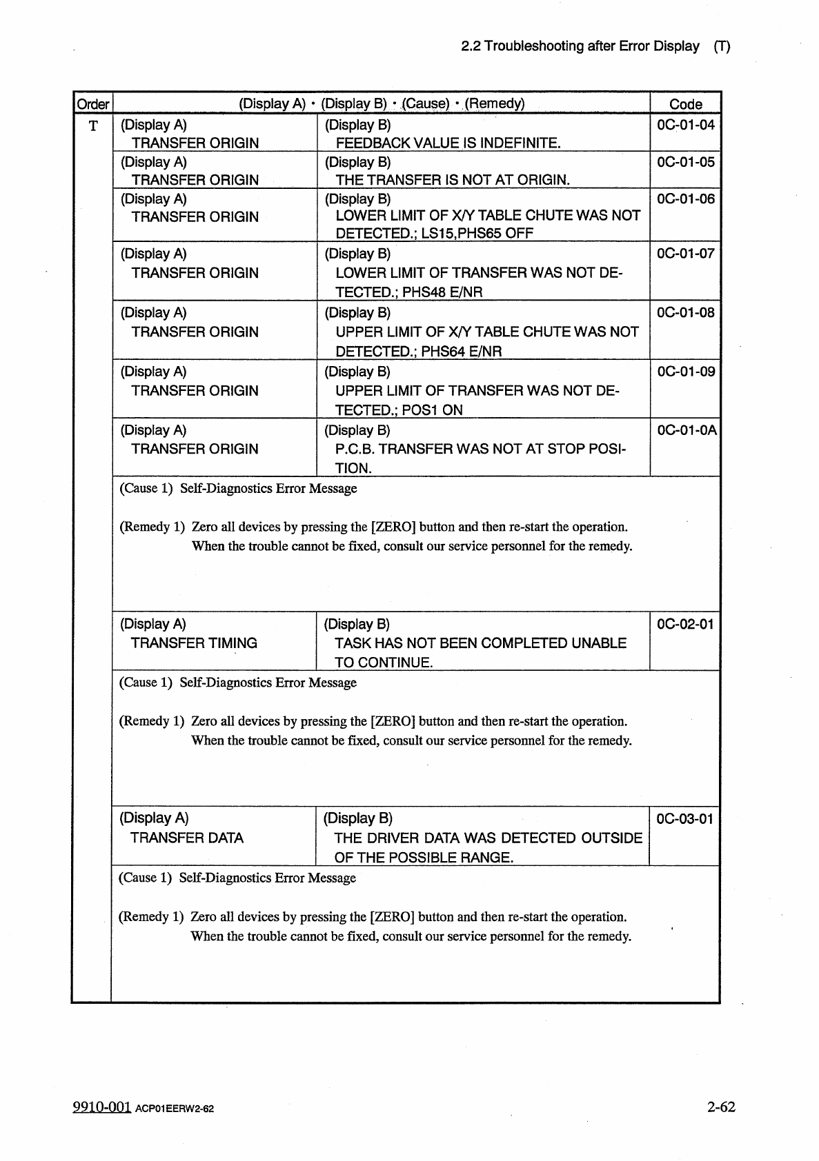
(
Display
A
)
TRANSFER
ORIGIN
(
Display
B
)
FEEDBACK
VALUE
IS
INDEFINITE
.
0001
-
04
T
(
Display
A
)
TRANSFER
ORIGIN
0
C
-
01
-
05
(
Display
B
)
THE
TRANSFER
IS
NOT
AT
ORIGIN
.
(
Display
A
)
TRANSFER
ORIGIN
(
Display
B
)
LOWER
LIMIT
OF
X
/
Y
TABLE
CHUTE
WAS
NOT
DETECTED
.
;
LS
15
.
PHS
65
OFF
0
C
-
01
-
06
0
C
-
01
-
07
(
Display
A
)
TRANSFER
ORIGIN
(
Display
B
)
LOWER
LIMIT
OF
TRANSFER
WAS
NOT
DE
-
TECTED
.
;
PHS
48
E
/
NR
0
C
-
01
-
08
(
Display
A
)
TRANSFER
ORIGIN
(
Display
B
)
UPPER
LIMIT
OF
X
/
Y
TABLE
CHUTE
WAS
NOT
DETECTED
.
;
PHS
64
E
/
NR
(
Display
A
)
TRANSFER
ORIGIN
0
C
-
01
-
09
(
Display
B
)
UPPER
LIMIT
OF
TRANSFER
WAS
NOT
DE
-
TECTED
.
;
P
0
S
1
ON
(
Display
A
)
TRANSFER
ORIGIN
0
C
-
01
-
0
A
(
Display
B
)
P
.
C
.
B
.
TRANSFER
WAS
NOT
AT
STOP
POSI
-
TION
.
(
Cause
1
)
Self
-
Diagnostics
Error
Message
(
Remedy
1
)
Zero
all
devices
by
pressing
the
[
ZERO
]
button
and
then
re
-
start
the
operation
.
When
the
trouble
cannot
be
fixed
,
consult
our
service
personnel
for
the
remedy
.
(
Display
A
)
TRANSFER
TIMING
(
Display
B
)
TASK
HAS
NOT
BEEN
COMPLETED
UNABLE
TO
CONTINUE
.
0
C
-
02
-
01
(
Cause
1
)
Self
-
Diagnostics
Error
Message
(
Remedy
1
)
Zero
all
devices
by
pressing
the
[
ZERO
]
button
and
then
re
-
start
the
operation
.
When
the
trouble
cannot
be
fixed
,
consult
our
service
personnel
for
the
remedy
.
(
Display
A
)
TRANSFER
DATA
(
Display
B
)
THE
DRIVER
DATA
WAS
DETECTED
OUTSIDE
OF
THE
POSS
旧
LE
RANGE
.
0
C
-
03
-
01
(
Cause
1
)
Self
-
Diagnostics
Error
Message
(
Remedy
1
)
Zero
all
devices
by
pressing
the
[
ZERO
]
button
and
then
re
-
start
the
operation
.
When
the
trouble
cannot
be
fixed
,
consult
our
service
personnel
for
the
remedy
.
9910
-
001
ACP
01
EERW
2
-
62
2
-
62