5TROUBLESHOOTING_.pdf - 第83页
2.2 Troubleshooting after Error Display ( T ) ( Display A ) • ( Display B ) • ( Cause ) • ( Remedy ) Order Code ( Display A ) TRANSFER LIMIT T ( Display B ) ( + ) LIMIT ERROR HAS BEEN DETECTED . ; PHS 44 E / NR 0004 - 01…
2.2
Troubleshooting
after
Error
Display
(
T
)
(
Display
A
)
•
(
Display
B
)
■
(
Gauge
)
•
(
Remedy
)
Order
Code
(
Display
A
)
TRANSFER
ORIGIN
(
Display
B
)
FEEDBACK
VALUE
IS
INDEFINITE
.
0001
-
04
T
(
Display
A
)
TRANSFER
ORIGIN
0
C
-
01
-
05
(
Display
B
)
THE
TRANSFER
IS
NOT
AT
ORIGIN
.
(
Display
A
)
TRANSFER
ORIGIN
(
Display
B
)
LOWER
LIMIT
OF
X
/
Y
TABLE
CHUTE
WAS
NOT
DETECTED
.
;
LS
15
.
PHS
65
OFF
0
C
-
01
-
06
0
C
-
01
-
07
(
Display
A
)
TRANSFER
ORIGIN
(
Display
B
)
LOWER
LIMIT
OF
TRANSFER
WAS
NOT
DE
-
TECTED
.
;
PHS
48
E
/
NR
0
C
-
01
-
08
(
Display
A
)
TRANSFER
ORIGIN
(
Display
B
)
UPPER
LIMIT
OF
X
/
Y
TABLE
CHUTE
WAS
NOT
DETECTED
.
;
PHS
64
E
/
NR
(
Display
A
)
TRANSFER
ORIGIN
0
C
-
01
-
09
(
Display
B
)
UPPER
LIMIT
OF
TRANSFER
WAS
NOT
DE
-
TECTED
.
;
P
0
S
1
ON
(
Display
A
)
TRANSFER
ORIGIN
0
C
-
01
-
0
A
(
Display
B
)
P
.
C
.
B
.
TRANSFER
WAS
NOT
AT
STOP
POSI
-
TION
.
(
Cause
1
)
Self
-
Diagnostics
Error
Message
(
Remedy
1
)
Zero
all
devices
by
pressing
the
[
ZERO
]
button
and
then
re
-
start
the
operation
.
When
the
trouble
cannot
be
fixed
,
consult
our
service
personnel
for
the
remedy
.
(
Display
A
)
TRANSFER
TIMING
(
Display
B
)
TASK
HAS
NOT
BEEN
COMPLETED
UNABLE
TO
CONTINUE
.
0
C
-
02
-
01
(
Cause
1
)
Self
-
Diagnostics
Error
Message
(
Remedy
1
)
Zero
all
devices
by
pressing
the
[
ZERO
]
button
and
then
re
-
start
the
operation
.
When
the
trouble
cannot
be
fixed
,
consult
our
service
personnel
for
the
remedy
.
(
Display
A
)
TRANSFER
DATA
(
Display
B
)
THE
DRIVER
DATA
WAS
DETECTED
OUTSIDE
OF
THE
POSS
旧
LE
RANGE
.
0
C
-
03
-
01
(
Cause
1
)
Self
-
Diagnostics
Error
Message
(
Remedy
1
)
Zero
all
devices
by
pressing
the
[
ZERO
]
button
and
then
re
-
start
the
operation
.
When
the
trouble
cannot
be
fixed
,
consult
our
service
personnel
for
the
remedy
.
9910
-
001
ACP
01
EERW
2
-
62
2
-
62
2.2
Troubleshooting
after
Error
Display
(
T
)
(
Display
A
)
•
(
Display
B
)
•
(
Cause
)
•
(
Remedy
)
Order
Code
(
Display
A
)
TRANSFER
LIMIT
T
(
Display
B
)
(
+
)
LIMIT
ERROR
HAS
BEEN
DETECTED
.
;
PHS
44
E
/
NR
0004
-
01
(
Cause
1
)
The
emitted
optical
beam
was
not
received
by
the
sensor
or
the
light
shield
plate
.
Dirt
adheres
to
the
light
shield
plate
and
an
optical
beam
of
the
sensor
is
shielded
.
(
Remedy
1
)
Press
the
[
RESET
]
button
to
cancel
the
error
,
open
the
front
cover
,
and
check
the
P
.
C
.
B
.
trans
-
fer
operation
through
manual
step
operation
.
Remove
the
cause
due
to
which
the
emitted
optical
beam
was
not
received
by
the
sensor
or
the
light
shield
plate
.
(
Display
A
)
TRANSFER
LIMIT
(
Display
B
)
(
•
)
LIMIT
ERROR
HAS
BEEN
DETECTED
.
;
PHS
45
E
/
NR
0
C
-
04
-
02
(
Cause
1
)
The
emitted
optical
beam
was
not
received
by
the
sensor
or
the
light
shield
plate
.
Dirt
adheres
to
the
light
shield
plate
and
an
optical
beam
of
the
sensor
is
shielded
.
(
Remedy
1
)
Press
the
[
RESET
]
button
to
cancel
the
error
,
open
the
front
cover
,
and
check
the
P
.
C
.
B
.
trans
-
fer
operation
through
manual
step
operation
.
Remove
the
cause
due
to
which
the
emitted
optical
beam
was
not
received
by
the
sensor
or
the
light
shield
plate
.
Zero
the
P
.
C
.
B
.
transfer
again
.
(
Display
A
)
TRANSFER
OVERLOAD
(
Display
B
)
OVERLOAD
HAS
BEEN
DETECTED
.
;
PHS
46
E
/
NR
0
C
-
05
-
01
(
Display
A
)
TRANSFER
OVERLOAD
(
Display
B
)
OVERLOAD
HAS
BEEN
DETECTED
.
;
LS
11
OFF
0
C
-
05
-
02
(
Cause
1
)
The
timing
belt
was
trapped
by
something
during
P
.
C
.
B
.
transfer
operation
and
got
loose
,
shielding
the
optical
beam
emitted
from
the
sensor
.
(
Remedy
1
)
Press
the
[
RESET
]
button
to
cancel
the
error
and
remove
the
cause
due
to
which
the
timing
belt
was
trapped
.
Then
,
zero
the
P
.
C
.
B
.
transfer
.
9910
-
001
ACP
01
EERW
2
-
63
2
-
63
2.2
Troubleshooting
after
Error
Display
(
T
)
(
Display
A
)
•
(
Display
B
)
•
(
Cause
)
•
(
Remedy
)
Order
Code
(
Display
A
)
TRANSFER
P
.
C
.
B
.
DETEC
-
T
(
Display
B
)
THE
P
.
C
.
B
.
HAS
NOT
PASSED
FROM
THE
IN
-
PUT
CONVEYOR
INTO
TABLE
CHUTE
.
0
C
-
06
-
01
TION
(
Cause
1
)
The
P
.
C
.
B
.
detection
photosensor
of
the
transfer
conveyor
detects
a
P
.
C
.
B
.
all
the
time
during
P
.
C
.
B
.
transfer
operation
.
(
The
P
.
C
.
B
.
is
not
transferred
.
)
(
Remedy
1
)
Press
the
[
RESET
]
button
to
cancel
the
error
and
remove
the
cause
due
to
which
the
P
.
C
.
B
.
is
not
transferred
.
•
When
the
sensitivity
of
the
sensor
is
too
high
,
decrease
the
sensitivity
.
•
Adjust
the
sensor
position
when
it
is
not
correct
.
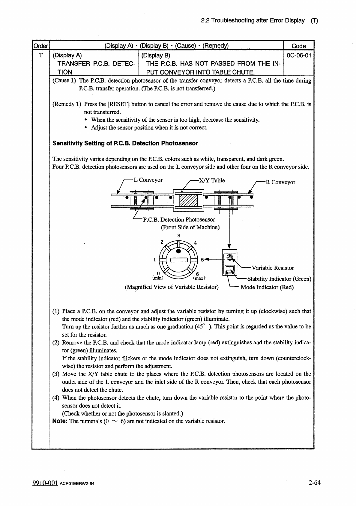
Sensitivity
Setting
of
P
.
C
.
B
.
Detection
Photosensor
The
sensitivity
varies
depending
on
the
P
.
C
.
B
Four
P
.
C
.
B
.
detection
photosensors
are
used
L
/
L
Conveyor
3
.
colors
on
the
L
such
as
white
,
transparent
,
and
dark
green
,
conveyor
side
and
other
four
on
theR
conveyor
side
.
■
X
/
Y
Table
R
Conveyor
L
P
.
C
.
B
.
Detection
Photosensor
(
Front
Side
of
Machine
)
Variable
Resistor
一
Stability
Indicator
(
Green
)
Mode
Indicator
(
Red
)
(
Magnified
View
of
Variable
Resistor
)
(
1
)
Place
a
P
.
C
.
B
.
on
the
conveyor
and
adjust
the
variable
resistor
by
turning
it
up
(
clockwise
)
such
that
the
mode
indicator
(
red
)
and
the
stability
indicator
(
green
)
illuminate
.
Turnup
the
resistor
further
as
much
as
one
graduation
(
45
°
)
.
This
point
is
regarded
as
the
value
to
be
set
for
the
resistor
.
(
2
)
Remove
the
P
.
C
.
B
.
and
check
that
the
mode
indicator
lamp
(
red
)
extinguishes
and
the
stability
indica
-
tor
(
green
)
illuminates
.
If
the
stability
indicator
flickers
or
the
mode
indicator
does
not
extinguish
,
turn
down
(
counterclock
-
wise
)
the
r
⑶
Move
the
outlet
side
of
the
L
conveyor
and
the
inlet
side
of
the
R
conveyor
.
Then
,
check
that
each
photosensor
does
not
detect
the
chute
.
(
4
)
When
the
photosensor
detects
the
chute
,
turn
down
the
variable
resistor
to
the
point
where
the
photo
-
sensor
does
not
detect
it
.
(
Check
whether
or
not
the
photosensor
is
slanted
.
)
Note
:
The
numerals
(
0
6
)
are
not
indicated
on
the
variable
resistor
.
and
perform
the
adjustment
.
able
chute
to
the
places
where
the
P
.
C
.
B
.
detection
photosensors
are
located
on
the
esistor
X
/
Y
U
2
-
64
9910
-
001
ACP
01
EERW
2
-
64