5TROUBLESHOOTING_.pdf - 第87页
2.2 Troubleshooting after Error Display ( T ) ( Display A ) • ( Display B ) • ( C ^ use ) • ( Remedy ) Order Code ( Display A ) TRANSFER INTERLOCK ( Display B ) TRANSFER UNABLE TO WORK BECAUSE OUTPUT CONVEYOR WAS NOT RUN…
2.2
Troubleshooting
after
Error
Display
(
T
)
(
Display
A
)
•
(
Display
B
)
■
(
Cause
)
■
(
Remedy
)
Order
Code
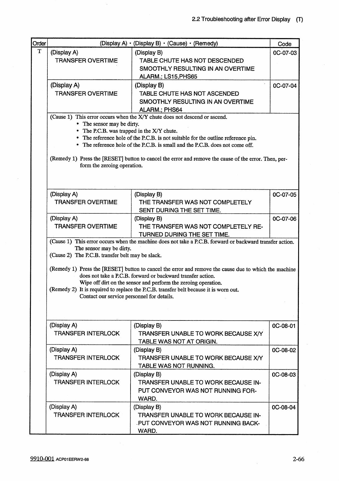
T
(
Display
A
)
TRANSFER
OVERTIME
(
Display
B
)
TABLE
CHUTE
HAS
NOT
DESCENDED
SMOOTHLY
RESULTING
IN
AN
OVERTIME
ALARM
.
;
LS
15
,
PHS
65
0007
-
03
(
Display
A
)
TRANSFER
OVERTIME
(
Display
B
)
TABLE
CHUTE
HAS
NOT
ASCENDED
SMOOTHLY
RESULTING
IN
AN
OVERTIME
0
C
-
07
-
04
ALARM
.
;
PHS
64
(
Cause
1
)
This
error
occurs
when
the
X
/
Y
chute
does
not
descend
or
ascend
.
•
The
sensor
may
be
dirty
.
•
The
P
.
CB
.
was
trapped
in
the
X
/
Y
chute
.
•
The
reference
hole
of
the
P
.
CB
.
is
not
suitable
for
the
outline
reference
pin
.
•
The
reference
hole
of
the
P
.
CB
.
is
small
and
the
P
.
CB
.
does
not
come
off
.
(
Remedy
1
)
Press
the
[
RESET
]
button
to
cancel
the
error
and
remove
the
cause
of
the
error
.
Then
,
per
-
form
the
zeroing
operation
.
(
Display
A
)
TRANSFER
OVERTIME
(
Display
B
)
THE
TRANSFER
WAS
NOT
COMPLETELY
SENT
DURING
THE
SET
TIME
.
0
C
-
07
-
05
(
Display
A
)
TRANSFER
OVERTIME
(
Display
B
)
THE
TRANSFER
WAS
NOT
COMPLETELY
RE
-
TURNED
DURING
THE
SET
TIME
.
0
C
-
07
-
06
(
Cause
1
)
This
error
occurs
when
the
machine
does
not
take
a
P
.
CB
.
forward
or
backward
transfer
action
.
The
sensor
may
be
dirty
.
(
Cause
2
)
The
P
.
CB
.
transfer
belt
may
be
slack
.
(
Remedy
1
)
Press
the
[
RESET
]
button
to
cancel
the
error
and
remove
the
cause
due
to
which
the
machine
does
not
take
a
P
.
CB
.
forward
or
backward
transfer
action
.
Wipe
off
dirt
on
the
sensor
and
perform
the
zeroing
operation
.
(
Remedy
2
)
It
is
required
to
replace
the
P
.
CB
.
transfer
belt
because
it
is
worn
out
.
Contact
our
service
personnel
for
details
.
(
Display
A
)
TRANSFER
INTERLOCK
(
Display
B
)
TRANSFER
UNABLE
TO
WORK
BECAUSE
X
/
Y
TABLE
WAS
NOT
AT
ORIGIN
.
0
C
-
08
-
01
(
Display
A
)
TRANSFER
INTERLOCK
(
Display
B
)
TRANSFER
UNABLE
TO
WORK
BECAUSE
X
/
Y
TABLE
WAS
NOT
RUNNING
.
0
C
-
08
-
02
(
Display
A
)
TRANSFER
INTERLOCK
(
Display
B
)
TRANSFER
UNABLE
TO
WORK
BECAUSE
IN
-
PUT
CONVEYOR
WAS
NOT
RUNNING
FOR
-
WARD
.
0
C
-
08
-
03
(
Display
A
)
TRANSFER
INTERLOCK
(
Display
B
)
TRANSFER
UNABLE
TO
WORK
BECAUSE
IN
-
PUT
CONVEYOR
WAS
NOT
RUNNING
BACK
-
WARD
.
0
C
-
08
-
04
9910
-
001
2
-
66
ACP
01
EERW
2
-
66
2.2
Troubleshooting
after
Error
Display
(
T
)
(
Display
A
)
•
(
Display
B
)
•
(
C
^
use
)
•
(
Remedy
)
Order
Code
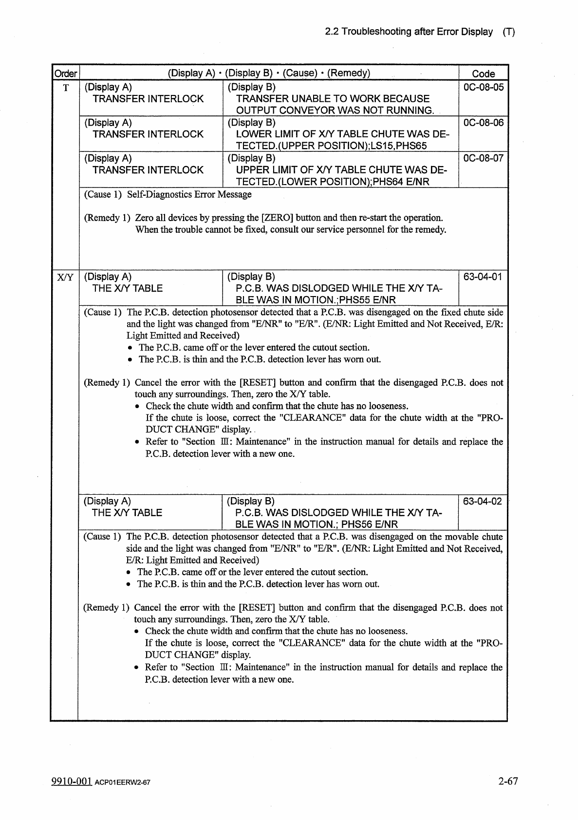
(
Display
A
)
TRANSFER
INTERLOCK
(
Display
B
)
TRANSFER
UNABLE
TO
WORK
BECAUSE
OUTPUT
CONVEYOR
WAS
NOT
RUNNING
.
0
C
-
08
-
05
T
(
Display
B
)
LOWER
LIMIT
OF
X
/
Y
TABLE
CHUTE
WAS
DE
-
TECTED
.
(
UPPER
P
0
S
1
TI
0
N
)
;
LS
15
,
PHS
65
(
Display
A
)
TRANSFER
INTERLOCK
0
C
-
08
-
06
(
Display
B
)
UPPER
LIMIT
OF
X
/
Y
TABLE
CHUTE
WAS
DE
-
TECTED
.
(
LOWER
POSITlON
)
;
PHS
64
E
/
NR
0
C
-
08
-
07
(
Display
A
)
TRANSFER
INTERLOCK
(
Cause
1
)
Self
-
Diagnostics
Error
Message
(
Remedy
1
)
Zero
all
devices
by
pressing
the
[
ZERO
]
button
and
then
re
-
start
the
operation
.
When
the
trouble
cannot
be
fixed
,
consult
our
service
personnel
for
the
remedy
.
(
Display
A
)
THE
X
/
Y
TABLE
(
Display
B
)
P
.
C
.
B
.
WAS
DISLODGED
WHILE
THE
X
/
Y
TA
-
BLE
WAS
IN
MOTION
.
;
PHS
55
E
/
NR
63
-
04
-
01
X
/
Y
(
Cause
1
)
The
P
.
C
.
B
.
detection
photosensor
detected
that
a
P
.
C
.
B
.
was
disengaged
on
the
fixed
chute
side
and
the
light
was
changed
from
”
E
/
NR
”
to
"
E
/
R
”
.
(
E
/
NR
:
Light
Emitted
and
Not
Received
,
E
/
R
:
Light
Emitted
and
Received
)
•
The
P
.
C
.
B
.
came
off
or
the
lever
entered
the
cutout
section
.
•
The
P
.
C
.
B
.
is
thin
and
the
P
.
C
.
B
.
detection
lever
has
worn
out
.
(
Remedy
1
)
Cancel
the
error
with
the
[
RESET
]
button
and
confirm
that
the
disengaged
P
.
C
.
B
.
does
not
touch
any
surroundings
.
Then
,
zero
the
X
/
Y
table
.
•
Check
the
chute
width
and
confirm
that
the
chute
has
no
looseness
.
If
the
chute
is
loose
,
correct
the
"
CLEARANCE
”
data
for
the
chute
width
at
the
"
PRO
-
DUCT
CHANGE
"
display
.
.
•
Refer
to
MSection
HI
:
Maintenance
”
in
the
instruction
manual
for
details
and
replace
the
P
.
C
.
B
.
detection
lever
with
a
new
one
.
(
Display
A
)
THE
X
/
Y
TABLE
(
Display
B
)
P
.
C
.
B
.
WAS
DISLODGED
WHILE
THE
X
/
Y
TA
-
BLE
WAS
IN
MOTION
.
;
PHS
56
E
/
NR
63
-
04
-
02
(
Cause
1
)
The
P
.
C
.
B
.
detection
photosensor
detected
that
a
P
.
C
.
B
.
was
disengaged
on
the
movable
chute
side
and
the
light
was
changed
from
”
E
/
NR
”
to
"
E
/
R
”
.
(
E
/
NR
:
Light
Emitted
and
Not
Received
,
E
/
R
:
Light
Emitted
and
Received
)
•
The
P
.
C
.
B
.
came
off
or
the
lever
entered
the
cutout
section
.
•
The
P
.
C
.
B
.
is
thin
and
the
P
.
C
.
B
.
detection
lever
has
worn
out
.
(
Remedy
1
)
Cancel
the
error
with
the
[
RESET
]
button
and
confirm
that
the
disengaged
P
.
C
.
B
.
does
not
touch
any
surroundings
.
Then
,
zero
the
X
/
Y
table
.
•
Check
the
chute
width
and
confirm
that
the
chute
has
no
looseness
.
If
the
chute
is
loose
,
correct
the
"
CLEARANCE
”
data
for
the
chute
width
at
the
"
PRO
-
DUCT
CHANGE
”
display
.
•
Refer
to
"
Section
3
H
:
Maintenance
"
in
the
instruction
manual
for
details
and
replace
the
P
.
C
.
B
.
detection
lever
with
a
new
one
.
2
-
67
9910
-
001
ACP
01
EERW
2
-
67
2.2
Troubleshooting
after
Error
Display
(
X
/
Y
)
(
Display
A
)
•
(
Display
B
)
•
(
Cause
)
v
(
Remedy
)
Order
Code
X
/
Y
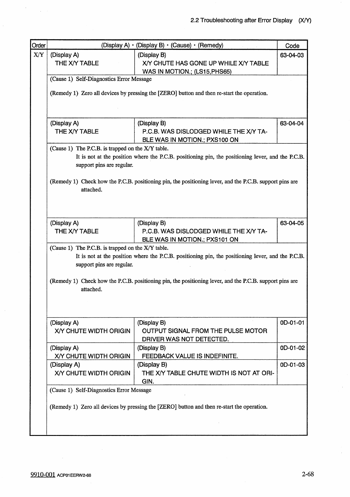
(
Display
A
)
THE
X
/
Y
TABLE
(
Display
B
)
X
/
Y
CHUTE
HAS
GONE
UP
WHILE
X
/
Y
TABLE
63
-
04
-
03
WAS
IN
MOTION
.
;
(
LS
15
,
PHS
65
)
(
Cause
1
)
Self
-
Diagnostics
Error
Message
(
Remedy
1
)
Zero
all
devices
by
pressing
the
[
ZERO
]
button
and
then
re
-
start
the
operation
.
(
Display
A
)
THE
X
/
Y
TABLE
(
Display
B
)
P
.
C
.
B
.
WAS
DISLODGED
WHILE
THE
X
/
Y
TA
-
BLE
WAS
IN
MOTION
.
;
PXS
100
ON
63
-
04
-
04
(
Cause
1
)
The
P
.
C
.
B
.
is
trapped
on
the
X
/
Y
table
.
It
is
not
at
the
position
where
the
P
.
C
.
B
.
positioning
pin
,
the
positioning
lever
,
and
the
P
.
C
.
B
.
support
pins
are
regular
.
(
Remedy
1
)
Check
how
the
P
.
C
.
B
.
positioning
pin
,
the
positioning
lever
,
and
the
P
.
C
.
B
.
support
pins
are
attached
.
(
Display
B
)
P
.
C
.
B
.
WAS
DISLODGED
WHILE
THE
X
/
Y
TA
-
BLE
WAS
IN
MOTION
.
;
PXS
101
ON
(
Display
A
)
THE
X
/
Y
TABLE
63
-
04
-
05
(
Cause
1
)
The
P
.
C
.
B
.
is
trapped
on
the
X
/
Y
table
.
It
is
not
at
the
position
where
the
P
.
C
.
B
.
positioning
pin
,
the
positioning
lever
,
and
the
P
.
C
.
B
.
support
pins
are
regular
.
(
Remedy
1
)
Check
how
the
P
.
C
.
B
.
positioning
pin
,
the
positioning
lever
,
and
the
P
.
C
.
B
.
support
pins
are
attached
.
(
Display
A
)
X
/
Y
CHUTE
WIDTH
ORIGIN
(
Display
B
)
OUTPUT
SIGNAL
FROM
THE
PULSE
MOTOR
DRIVER
WAS
NOT
DETECTED
.
0
D
-
01
-
01
(
Display
A
)
X
/
Y
CHUTE
WIDTH
ORIGIN
(
Display
B
)
FEEDBACK
VALUE
IS
INDEFINITE
.
0
D
-
01
-
02
(
Display
A
)
X
/
Y
CHUTE
WIDTH
ORIGIN
(
Display
B
)
THE
X
/
Y
TABLE
CHUTE
WIDTH
IS
NOT
AT
ORI
-
0
D
-
01
-
03
GIN
.
(
Cause
1
)
Self
-
Diagnostics
Error
Message
(
Remedy
1
)
Zero
all
devices
by
pressing
the
[
ZERO
]
button
and
then
re
-
start
the
operation
.
2
-
68
9910
-
001
ACP
01
EERW
2
-
68