5TROUBLESHOOTING_.pdf - 第89页
2.2 Troubleshooting after Error Display ( X / V ) ( Display A ) • ( Display B ) • ( Cauge ) * ( Remedy ) Code Order ( Display B ) TASK HAS NOT BEEN COMPLETED UNABLE TO CONTINUE . ( Display A ) X / Y CHUTE WIDTH TIMING 0 …
2.2
Troubleshooting
after
Error
Display
(
X
/
Y
)
(
Display
A
)
•
(
Display
B
)
•
(
Cause
)
v
(
Remedy
)
Order
Code
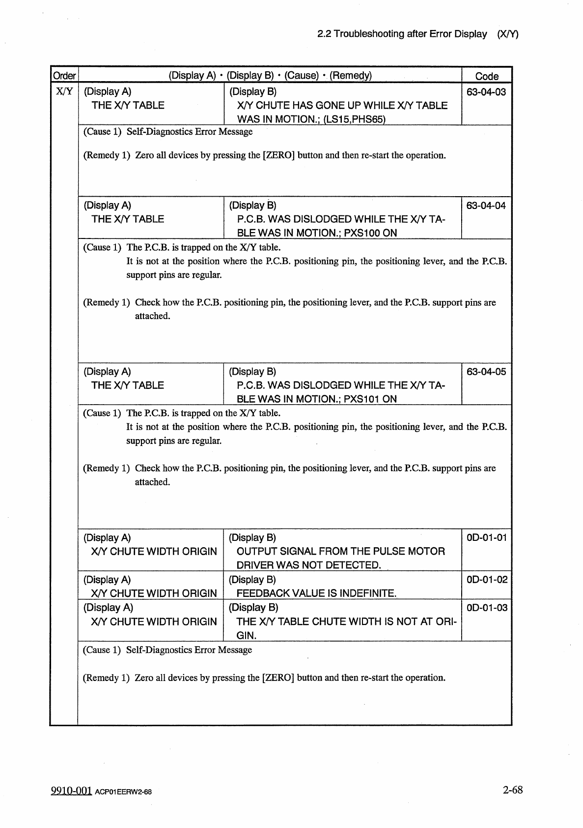
X
/
Y
(
Display
A
)
THE
X
/
Y
TABLE
(
Display
B
)
X
/
Y
CHUTE
HAS
GONE
UP
WHILE
X
/
Y
TABLE
63
-
04
-
03
WAS
IN
MOTION
.
;
(
LS
15
,
PHS
65
)
(
Cause
1
)
Self
-
Diagnostics
Error
Message
(
Remedy
1
)
Zero
all
devices
by
pressing
the
[
ZERO
]
button
and
then
re
-
start
the
operation
.
(
Display
A
)
THE
X
/
Y
TABLE
(
Display
B
)
P
.
C
.
B
.
WAS
DISLODGED
WHILE
THE
X
/
Y
TA
-
BLE
WAS
IN
MOTION
.
;
PXS
100
ON
63
-
04
-
04
(
Cause
1
)
The
P
.
C
.
B
.
is
trapped
on
the
X
/
Y
table
.
It
is
not
at
the
position
where
the
P
.
C
.
B
.
positioning
pin
,
the
positioning
lever
,
and
the
P
.
C
.
B
.
support
pins
are
regular
.
(
Remedy
1
)
Check
how
the
P
.
C
.
B
.
positioning
pin
,
the
positioning
lever
,
and
the
P
.
C
.
B
.
support
pins
are
attached
.
(
Display
B
)
P
.
C
.
B
.
WAS
DISLODGED
WHILE
THE
X
/
Y
TA
-
BLE
WAS
IN
MOTION
.
;
PXS
101
ON
(
Display
A
)
THE
X
/
Y
TABLE
63
-
04
-
05
(
Cause
1
)
The
P
.
C
.
B
.
is
trapped
on
the
X
/
Y
table
.
It
is
not
at
the
position
where
the
P
.
C
.
B
.
positioning
pin
,
the
positioning
lever
,
and
the
P
.
C
.
B
.
support
pins
are
regular
.
(
Remedy
1
)
Check
how
the
P
.
C
.
B
.
positioning
pin
,
the
positioning
lever
,
and
the
P
.
C
.
B
.
support
pins
are
attached
.
(
Display
A
)
X
/
Y
CHUTE
WIDTH
ORIGIN
(
Display
B
)
OUTPUT
SIGNAL
FROM
THE
PULSE
MOTOR
DRIVER
WAS
NOT
DETECTED
.
0
D
-
01
-
01
(
Display
A
)
X
/
Y
CHUTE
WIDTH
ORIGIN
(
Display
B
)
FEEDBACK
VALUE
IS
INDEFINITE
.
0
D
-
01
-
02
(
Display
A
)
X
/
Y
CHUTE
WIDTH
ORIGIN
(
Display
B
)
THE
X
/
Y
TABLE
CHUTE
WIDTH
IS
NOT
AT
ORI
-
0
D
-
01
-
03
GIN
.
(
Cause
1
)
Self
-
Diagnostics
Error
Message
(
Remedy
1
)
Zero
all
devices
by
pressing
the
[
ZERO
]
button
and
then
re
-
start
the
operation
.
2
-
68
9910
-
001
ACP
01
EERW
2
-
68
2.2
Troubleshooting
after
Error
Display
(
X
/
V
)
(
Display
A
)
•
(
Display
B
)
•
(
Cauge
)
*
(
Remedy
)
Code
Order
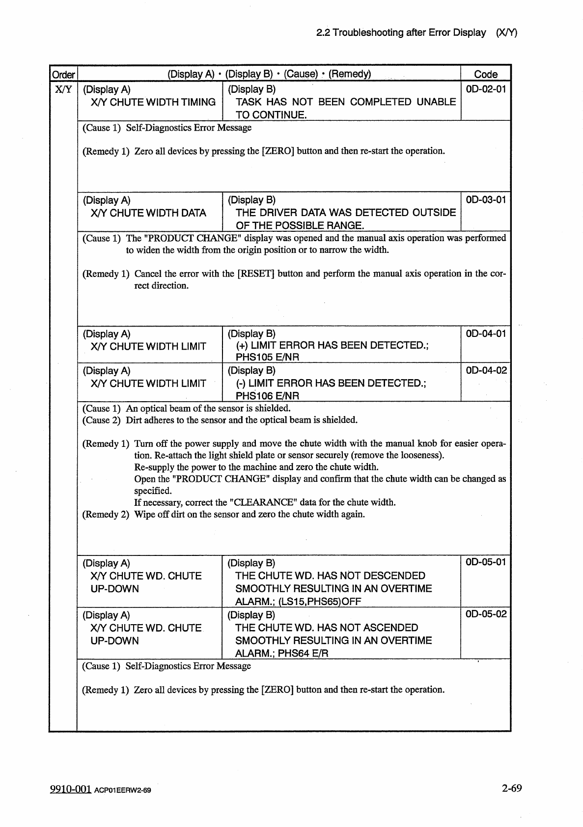
(
Display
B
)
TASK
HAS
NOT
BEEN
COMPLETED
UNABLE
TO
CONTINUE
.
(
Display
A
)
X
/
Y
CHUTE
WIDTH
TIMING
0
D
-
02
-
01
X
/
Y
(
Cause
1
)
Self
-
Diagnostics
Error
Message
(
Remedy
1
)
Zero
all
devices
by
pressing
the
[
ZERO
]
button
and
then
re
-
start
the
operation
.
(
Display
B
)
THE
DRIVER
DATA
WAS
DETECTED
OUTSIDE
OF
THE
POSSIBLE
RANGE
.
0
D
-
03
-
01
(
Display
A
)
X
/
Y
CHUTE
WIDTH
DATA
(
Cause
1
)
The
"
PRODUCT
CHANGE
"
display
was
opened
and
the
manual
axis
operation
was
performed
to
widen
the
width
from
the
origin
position
or
to
narrow
the
width
.
(
Remedy
1
)
Cancel
the
error
with
the
[
RESET
]
button
and
perform
the
manual
axis
operation
in
the
cor
-
rect
direction
.
(
Display
A
)
X
/
Y
CHUTE
WIDTH
LIMIT
(
Display
B
)
(
+
)
LIMIT
ERROR
HAS
BEEN
DETECTED
.
;
PHS
105
E
/
NR
0
D
-
04
-
01
(
Display
B
)
㈠
LIMIT
ERROR
HAS
BEEN
DETECTED
.
;
PHS
106
E
/
NR
0
D
-
04
-
02
(
Display
A
)
X
/
Y
CHUTE
WIDTH
LIMIT
(
Cause
1
)
An
optical
beam
of
the
sensor
is
shielded
.
(
Cause
2
)
Dirt
adheres
to
the
sensor
and
the
optical
beam
is
shielded
.
(
Remedy
1
)
Turn
off
the
power
supply
and
move
the
chute
width
with
the
manual
knob
for
easier
opera
-
tion
.
Re
-
attach
the
light
shield
plate
or
sensor
securely
(
remove
the
looseness
)
.
Re
-
supply
the
power
to
the
machine
and
zero
the
chute
width
.
Open
the
"
PRODUCT
CHANGE
*
'
display
and
confirm
that
the
chute
width
can
be
changed
as
specified
.
If
necessary
,
correct
the
"
CLEARANCE
"
data
for
the
chute
width
.
(
Remedy
2
)
Wipe
off
dirt
on
the
sensor
and
zero
the
chute
width
again
.
0
D
-
05
-
01
(
Display
B
)
THE
CHUTE
WD
.
HAS
NOT
DESCENDED
SMOOTHLY
RESULTING
IN
AN
OVERTIME
ALARM
.
;
(
LS
15
,
PHS
65
)
OFF
(
Display
A
)
X
/
Y
CHUTE
WD
.
CHUTE
UP
-
DOWN
0
D
-
05
-
02
(
Display
B
)
THE
CHUTE
WD
.
HAS
NOT
ASCENDED
SMOOTHLY
RESULTING
IN
AN
OVERTIME
ALARM
.
;
PHS
64
E
/
R
(
Display
A
)
X
/
Y
CHUTE
WD
.
CHUTE
UP
-
DOWN
(
Cause
1
)
Self
-
Diagnostics
Error
Message
(
Remedy
1
)
Zero
all
devices
by
pressing
the
[
ZERO
]
button
and
then
re
-
start
the
operation
.
2
-
69
9910
-
001
ACP
01
EERW
2
-
69
2.2
Troubleshooting
after
Error
Display
(
X
/
Y
)
(
Display
A
)
•
(
Display
B
)
•
(
Cause
)
•
(
Remedy
)
Order
Code
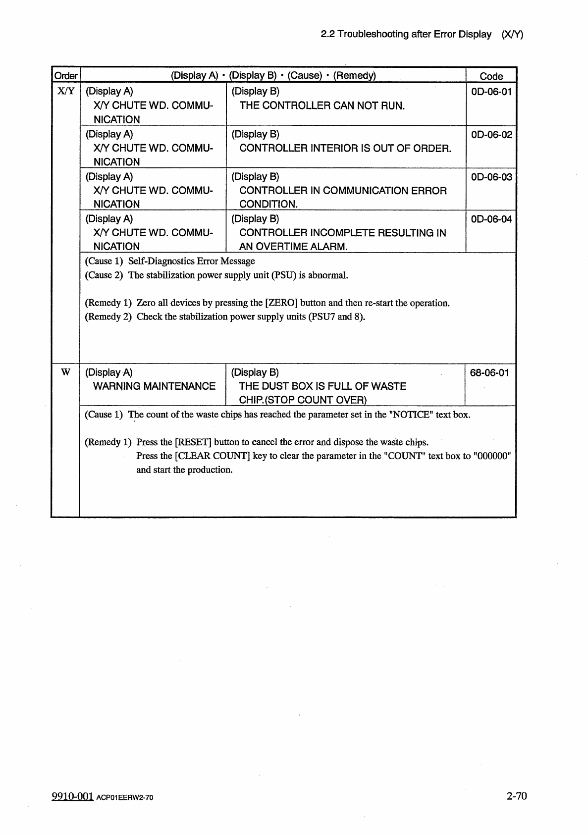
(
Display
A
)
X
/
Y
CHUTE
WD
_
COMMU
-
NICATION
(
Display
B
)
THE
CONTROLLER
CAN
NOT
RUN
.
X
/
Y
0
D
-
06
-
01
(
Display
A
)
X
/
Y
CHUTE
WD
.
COMMU
-
NICATION
(
Display
B
)
CONTROLLER
INTERIOR
IS
OUT
OF
ORDER
.
0
D
-
06
-
02
(
Display
A
)
X
/
Y
CHUTE
WD
.
COMMU
-
NICATION
(
Display
B
)
CONTROLLER
IN
COMMUNICATION
ERROR
CONDITION
.
0
D
-
06
-
03
(
Display
A
)
X
/
Y
CHUTE
WD
.
COMMU
-
NICATION
(
Display
B
)
CONTROLLER
INCOMPLETE
RESULTING
IN
AN
OVERTIME
ALARM
.
0
D
-
06
-
04
(
Cause
1
)
Self
-
Diagnostics
Error
Message
(
Cause
2
)
The
stabilization
power
supply
unit
(
PSU
)
is
abnormal
.
(
Remedy
1
)
Zero
all
devices
by
pressing
the
[
ZERO
]
button
and
then
re
-
start
the
operation
.
(
Remedy
2
)
Check
the
stabilization
power
supply
units
(
PSU
7
and
8
)
.
(
Display
A
)
WARNING
MAINTENANCE
(
Display
B
)
THE
DUST
BOX
IS
FULL
OF
WASTE
CH
1
R
(
STQP
COUNT
OVER
)
W
68
-
06
-
01
(
Cause
1
)
The
count
of
the
waste
chips
has
reached
the
parameter
set
in
the
"
NOTICE
"
text
box
.
(
Remedy
1
)
Press
the
[
RESET
]
button
to
cancel
the
error
and
dispose
the
waste
chips
.
Press
the
[
CLEAR
COUNT
]
key
to
clear
the
parameter
in
the
"
COUNT
”
text
box
to
”
000000
’
and
start
the
production
.
2
-
70
9910
-
001
ACP
01
EERW
2
-
70