5TROUBLESHOOTING_.pdf - 第91页
- 總 M 8 讎騰纖腿欲腿 k 麗丽腿臓 Page 3.1 Understanding the Contents of the “ ERROR ” Displays and the Troubleshooting Tables 3.1 . 1 “ ERROR ” Display 3.1 . 2 Troubleshooting 3.2 Basic System of Recognition Error Codes 3.3 Trouble…
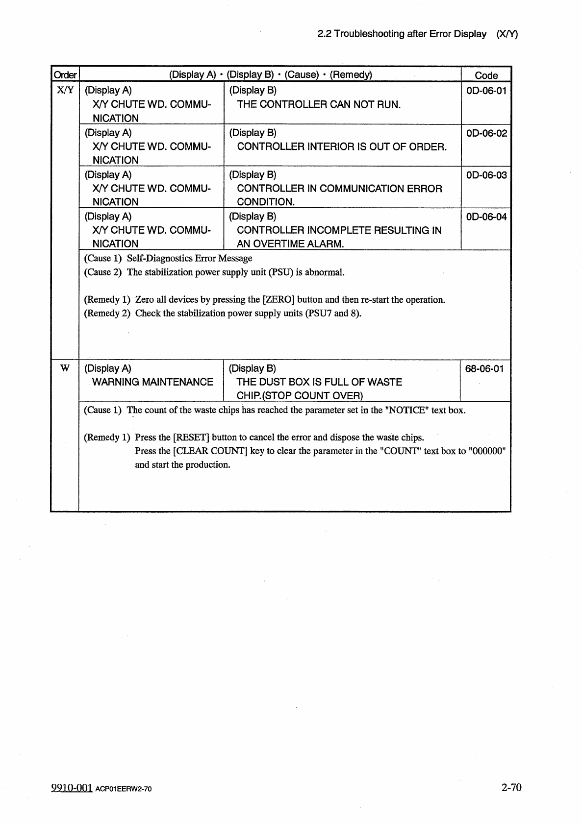
2.2
Troubleshooting
after
Error
Display
(
X
/
Y
)
(
Display
A
)
•
(
Display
B
)
•
(
Cause
)
•
(
Remedy
)
Order
Code
(
Display
A
)
X
/
Y
CHUTE
WD
_
COMMU
-
NICATION
(
Display
B
)
THE
CONTROLLER
CAN
NOT
RUN
.
X
/
Y
0
D
-
06
-
01
(
Display
A
)
X
/
Y
CHUTE
WD
.
COMMU
-
NICATION
(
Display
B
)
CONTROLLER
INTERIOR
IS
OUT
OF
ORDER
.
0
D
-
06
-
02
(
Display
A
)
X
/
Y
CHUTE
WD
.
COMMU
-
NICATION
(
Display
B
)
CONTROLLER
IN
COMMUNICATION
ERROR
CONDITION
.
0
D
-
06
-
03
(
Display
A
)
X
/
Y
CHUTE
WD
.
COMMU
-
NICATION
(
Display
B
)
CONTROLLER
INCOMPLETE
RESULTING
IN
AN
OVERTIME
ALARM
.
0
D
-
06
-
04
(
Cause
1
)
Self
-
Diagnostics
Error
Message
(
Cause
2
)
The
stabilization
power
supply
unit
(
PSU
)
is
abnormal
.
(
Remedy
1
)
Zero
all
devices
by
pressing
the
[
ZERO
]
button
and
then
re
-
start
the
operation
.
(
Remedy
2
)
Check
the
stabilization
power
supply
units
(
PSU
7
and
8
)
.
(
Display
A
)
WARNING
MAINTENANCE
(
Display
B
)
THE
DUST
BOX
IS
FULL
OF
WASTE
CH
1
R
(
STQP
COUNT
OVER
)
W
68
-
06
-
01
(
Cause
1
)
The
count
of
the
waste
chips
has
reached
the
parameter
set
in
the
"
NOTICE
"
text
box
.
(
Remedy
1
)
Press
the
[
RESET
]
button
to
cancel
the
error
and
dispose
the
waste
chips
.
Press
the
[
CLEAR
COUNT
]
key
to
clear
the
parameter
in
the
"
COUNT
”
text
box
to
”
000000
’
and
start
the
production
.
2
-
70
9910
-
001
ACP
01
EERW
2
-
70
-
總
M
8
讎騰纖腿欲腿
k
麗丽腿臓
Page
3.1
Understanding
the
Contents
of
the
“
ERROR
”
Displays
and
the
Troubleshooting
Tables
3.1
.
1
“
ERROR
”
Display
3.1
.
2
Troubleshooting
3.2
Basic
System
of
Recognition
Error
Codes
3.3
Troubleshooting
against
Recognition
Errors
•
-
3.3
.
1
Reset
Procedure
from
Component
Recognition
Error
3.3
.
2
Reset
Procedure
from
P
.
E
.
C
.
Recognition
Error
3.3
.
3
Reset
Procedure
from
Nozzle
Recognition
Error
3.3
.
4
Reset
Procedure
from
Camera
Offset
Recognition
Error
3.3
.
5
Reset
Procedure
from
Lighting
Check
Function
Error
3.3
.
6
Reset
Procedure
from
Camera
Gain
/
Level
Automatic
Setting
Function
Error
3.3
.
7
Reset
Procedure
from
Other
Recognition
Function
Errors
3
-
1
3
-
1
3
-
2
3
-
3
3
-
4
.
.
.
3
-
4
3
-
29
3
-
34
3
-
37
3
-
40
3
-
44
3
-
46
ACP
01
EERCC
3
3.1
Understanding
the
Contents
of
the
"
ERROR
"
Displays
and
the
Troubleshooting
Tables
3.1
Understanding
the
Contents
of
the
"
ERROR
"
Displays
and
the
Troubleshooting
Tables
3.1
.
1
"
ERROR
"
Display
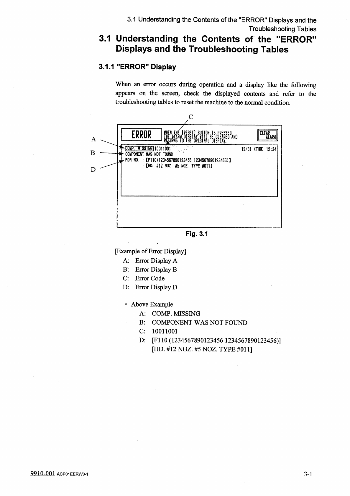
When
an
error
occurs
during
operation
and
a
display
like
the
following
appears
on
the
screen
,
check
the
displayed
contents
and
refer
to
the
troubleshooting
tables
to
reset
the
machine
to
the
normal
condition
.
C
IPS
A
hlSSIfJgllOQUOQI
二
:
二
:
rrFO
咖
FDR
NO
.
:
[
F
110
C
1234567890123456
1234567890123456
)
1
:
【
HD
.
#
12
NOZ
舫
NOZ
.
TYPE
#
011
】
12
/
31
(
THU
)
12
:
34
|
B
D
Fig
.
3.1
[
Example
of
Error
Display
]
A
:
Error
Display
A
B
:
Error
Display
B
C
:
Error
Code
D
:
Error
Display
D
•
Above
Example
A
:
COMP
.
MISSING
B
:
COMPONENT
WAS
NOT
FOUND
C
:
10011001
D
:
[
FI
10
(
1234567890123456
1234567890123456
)
]
[
HD
.
#
12
NOZ
.
#
5
NOZ
.
TYPE
#
011
]
9910
-
001
ACP
01
EERW
3
-
1
3
-
1