2500_Users_Manual-.pdf - 第110页
↵ ↵ ↵ Tasks and Kits Description : Source Database : Task/Quant Ta$kL ink ] Copyright 1993 Data I/O Corp. =| Add Kit |= Edit Kit "KIT 1" TaskLink Copyright 1934 Data I/O Corp. ==| Add Kit | Edit Kit "KIT 1…
1958-2
Run Kit
Perform all Tasks in Kit
Number of Kits to Build
Session I.D.
Device
Process
•
•
•
•
•
Specify
Task 1
Task 2
Task 3
Task 4
Message
~0001
Message
~0002
Message
~0003
Tasks
and
Kits
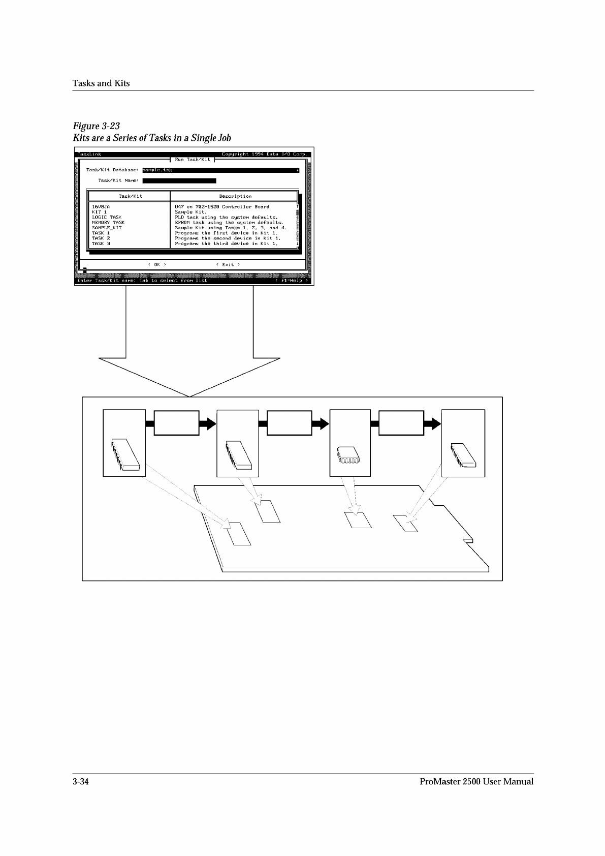
Figure
3-23
Kits
are
a
Series
of
Tasks
in
a
Single
Job
TaskLi
nk
Copyright
1994
Data
I/O
Corp.
Run
Task/Kit
Enter
Task/Kit
Tab
to
select
frou
list
<
Fl=Help
3-34
ProMaster
2500
User
Manual
↵
↵
↵
Tasks
and
Kits
Description
:
Source
Database
:
Task/Quant
Ta$kL
ink
]
Copyright
1993
Data
I/O
Corp.
=|
Add
Kit
|=
Edit
Kit
"KIT
1"
TaskLink
Copyright
1934
Data
I/O
Corp.
==|
Add
Kit
|
Edit
Kit
"KIT
1"
p
ISanple
Kit.
Source
Database:
|c;
\tl\sanpl
巳.
twk
<
Message
Editor
〉
<
Cance
1
>
Press
Enter
to
accept
dialog;
Tab
for
next
item
<
Fl=Help
〉
<
Message
Editor
> <
Save
> <
Cancel
>
Enter
text;
Tab
f
or
next
<
Fl=Help
>
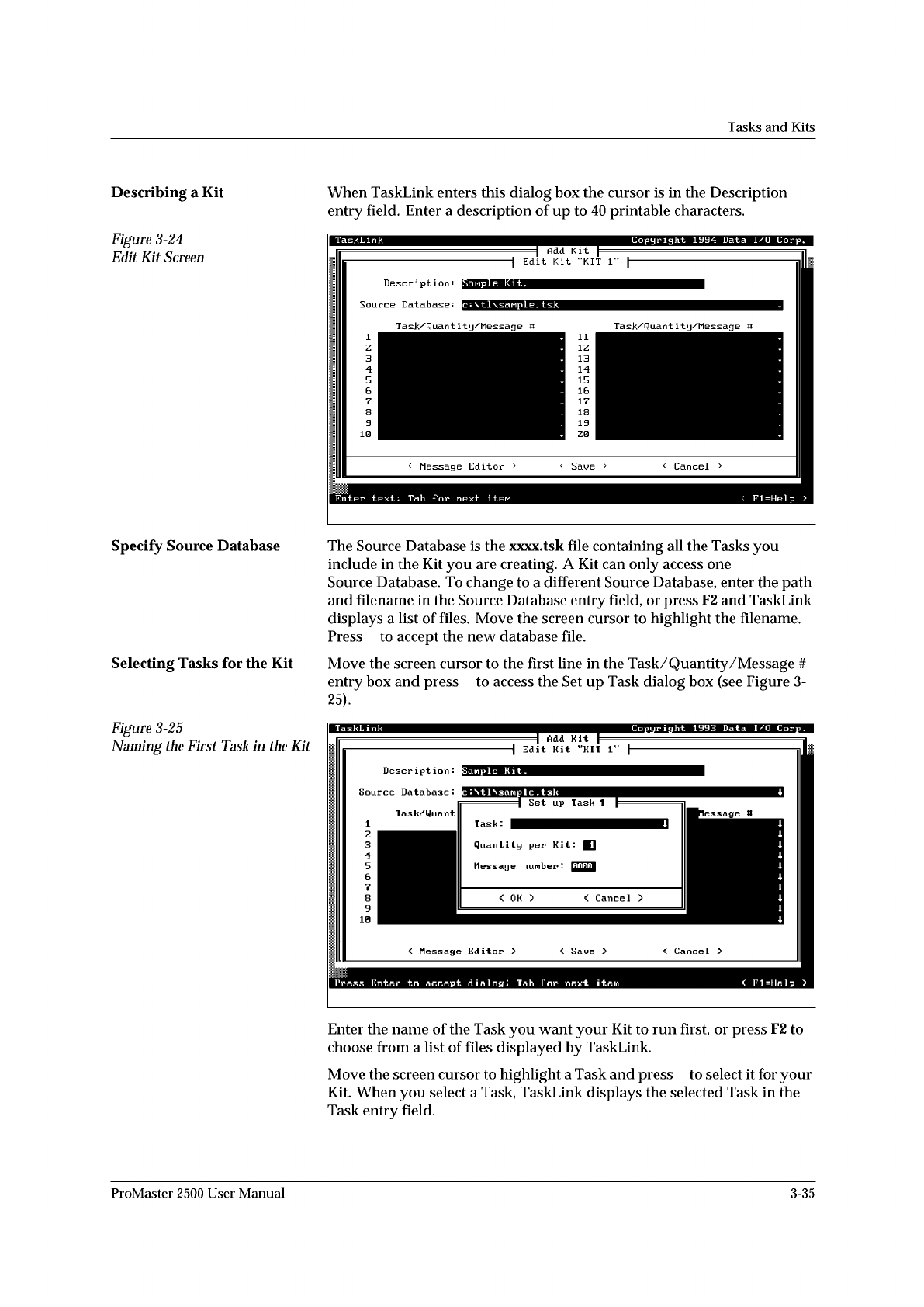
Describing
a
Kit
Figure
3-24
Edit
Kit
Screen
When
TaskLink
enters
this
dialog
box
the
cursor
is
in
the
Description
entry
field.
Enter
a
description
of
up
to
40
printable
characters.
Specify
Source
Database
Selecting
Tasks
for
the
Kit
The
Source
Database
is
the
xxxx.tsk
file
containing
all
the
Tasks
you
include
in
the
Kit
you
are
creating.
A
Kit
can
only
access
one
Source
Database.
To
change
to
a
different
Source
Database,
enter
the
path
and
filename
in
the
Source
Database
entry
field,
or
press
F2
and
TaskLink
displays
a
list
of
files.
Move
the
screen
cursor
to
highlight
the
filename.
Press
to
accept
the
new
database
file.
Move
the
screen
cursor
to
the
first
line
in
the
Task/Quantity
/Message
#
entry
box
and
press
to
access
the
Set
up
Task
dialog
box
(see
Figure
3-
25).
Figure
3-25
Naming
the
First
TasA
in
the
Kit
Enter
the
name
of
the
Task
you
want
your
Kit
to
run
first,
or
press
F2
to
choose
from
a
list
of
files
displayed
by
TaskLink.
Move
the
screen
cursor
to
highlight
a
Task
and
press
to
select
it
for
your
Kit.
When
you
select
a
Task,
TaskLink
displays
the
selected
Task
in
the
Task
entry
field.
1234567890
1
ProMaster
2500
User
Manual
3-35
*
)
1670-1
X1
X3
X2 X4
X1
X3
X2 X4
X1
X3
X2 X4
28C
28E
28D 28B
PLCC 28-5
PLCC 28-1 PLCC 28-2 PLCC 28-3 PLCC 28-4
28A 28A
X1
X3
X2 X4
28B 28A
X1
X3
X2 X4
28A
28A
= NO CONFIGURATION BLOCK
Operation
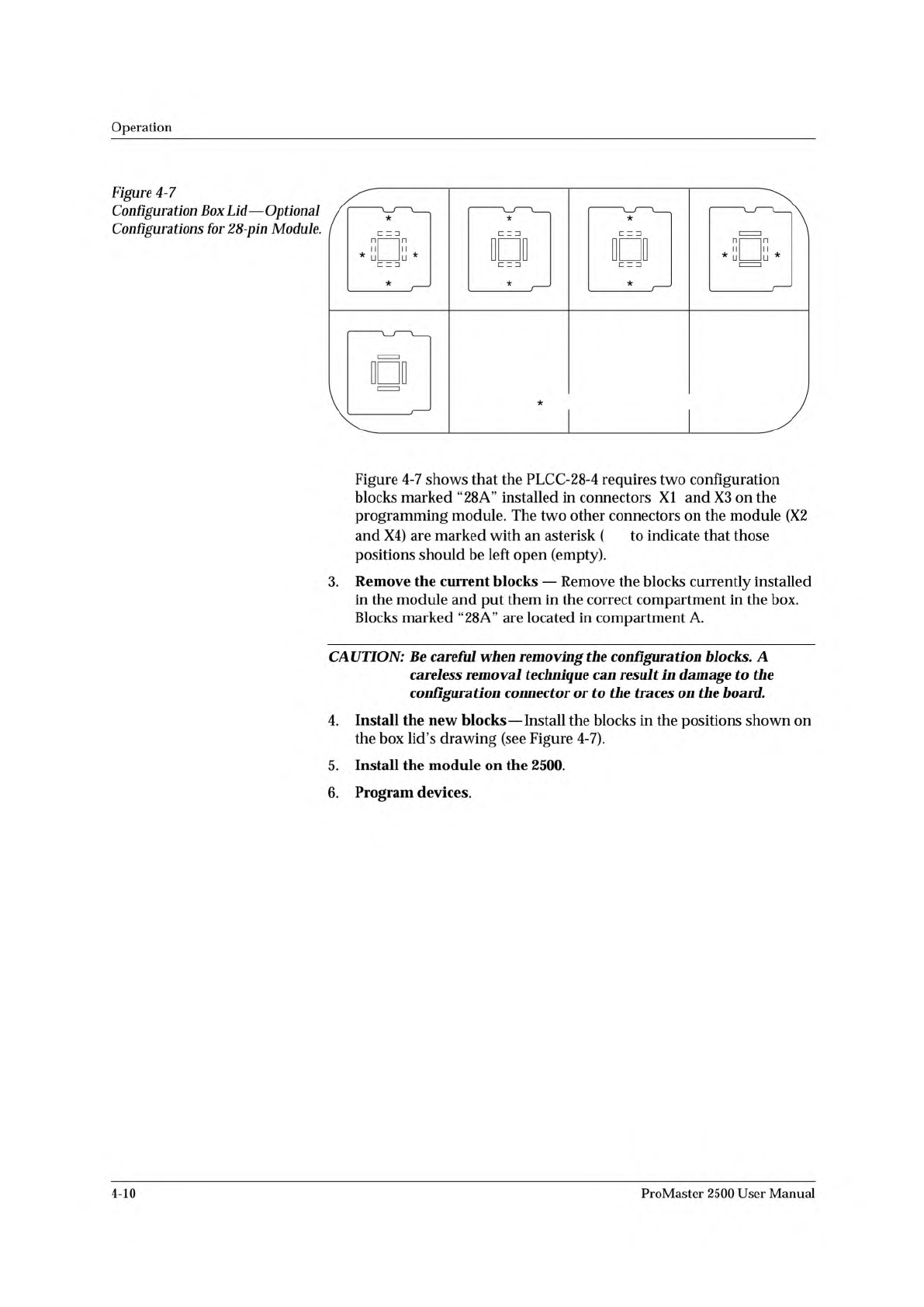
Figure
4-7
Configuration
Box
Lid
—
Optional
Configurations
for
28-pin
Module.
Figure
4-7
shows
that
the
PLCC-28-4
requires
two
configuration
blocks
marked
“28
A”
installed
in
connectors
XI
and
X3
on
the
programming
module.
The
two
other
connectors
on
the
module
(X2
and
X4)
are
marked
with
an
asterisk
(
to
indicate
that
those
positions
should
be
left
open
(empty).
3.
Remove
the
current
blocks
—
Remove
the
blocks
currently
installed
in
the
module
and
put
them
in
the
correct
compartment
in
the
box.
Blocks
marked
“28A”
are
located
in
compartment
A.
CAUTION:
Be
careful
when
removing
the
configuration
blocks.
A
careless
removal
technique
can
result
加
damage
to
the
configuration
connector
or
to
the
traces
on
the
board.
4.
Install
the
new
blocks
—
Install
the
blocks
in
the
positions
shown
on
the
box
lid's
drawing
(see
Figure
4-7).
5.
Install
the
module
on
the
2500.
6.
Program
devices.
4-10
ProMaster
2500
User
Manual