2500_Users_Manual-.pdf - 第124页
Operation If you start a Task with an incorrect number in the Parts /tube field, press STOP and then LOWER CASE + T. Enter the correct number. Press ENTER and then START to continue running the Task. This screen also ind…
Part Programmer Package Prod.
Mfr. Number Menu Name Pins Type Footnotes Base Vers.
XXX 22V10-10/-15 22V10-10-PLCC 28 PLCC 3 PLCC-28-2 1.1
XXX CE26V12H CE26V12H-PL 28 PLCC 53 PLCC-28-4 1.1
A B C D
E
F G H
1680-1
Operation
Removing
Modules
or
Moving
Configuration
Blocks
This
section
describes
the
typical
steps
involved
in
checking
and
changing
the
configuration
of
your
module.
1.
Select
the
device
—
On
the
Device
List
disk,
find
the
device
you
want
to
program
in
the
left-hand
columns.
The
module
configuration
for
that
device
is
listed
in
the
column
labeled
“Base.”
Sample
lines
from
the
Device
List
disk
are
shown
below:
Most
devices
are
programmed
with
the
“-2”
programming
module
configuration
because
it
supports
standard
power
and
ground
pin
locations.
For
this
sample
procedure,
the
selected
device
requires
“PLCC-28-4”
for
the
programming
module
configuration.
This
means
that
the
device
is
in
a
PLCC
package,
has
28
pins,
and
must
be
configured
as
a
“-4.”
Note:
Modules
are
shipped
from
the
factory
without
any
configuration
blocks
installed
(the
configuration).
Check
the
ProMaster
2500
Device
List
disk
for
the
specific
configuration
required
for
the
devices
you
will
be
programming.
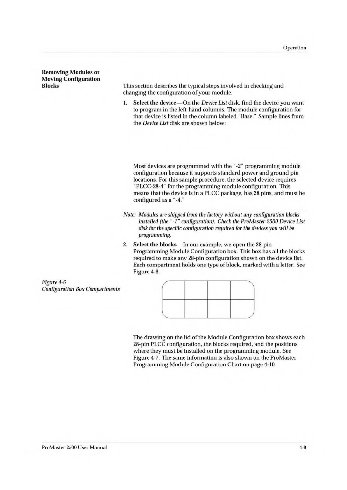
2.
Select
the
blocks
—
In
our
example,
we
open
the
28-pin
Programming
Module
Configuration
box.
This
box
has
all
the
blocks
required
to
make
any
28-pin
configuration
shown
on
the
device
list.
Each
compartment
holds
one
type
of
block,
marked
with
a
letter.
See
Figure
4-6.
Figure
4-6
Configuration
Box
Compartments
The
drawing
on
the
lid
of
the
Module
Configuration
box
shows
each
28-pin
PLCC
configuration,
the
blocks
required,
and
the
positions
where
they
must
be
installed
on
the
programming
module.
See
Figure
4-7.
The
same
information
is
also
shown
on
the
ProMaster
Programming
Module
Configuration
Chart
on
page
4-10
ProMaster
2500
User
Manual
4-9
Operation
If
you
start
a
Task
with
an
incorrect
number
in
the
Parts
/tube
field,
press
STOP
and
then
LOWER
CASE
+
T.
Enter
the
correct
number.
Press
ENTER
and
then
START
to
continue
running
the
Task.
This
screen
also
indicates
where
TaskLink
expects
device
pin
1
to
be
located
when
the
device
is
in
the
input
track.
This
is
critical
for
correct
device
handling
and
insertion
in
the
programming
module
socket.
Make
certain
that
your
device
matches
this
positioning.
Refer
to
page
4-22
for
more
information
on
installing
devices
in
the
input
tube
holder.
The
system
automatically
downloads
the
data
file
defined
in
your
Task
or
prompts
you
to
insert
a
master
device.
If
the
Task
asks
you
to
load
RAM
data
from
a
master
device,
TaskLink
prompts
you
to
insert
the
master
device
to
be
loaded.
Place
the
device
in
the
input
track,
against
the
programming
station
stop
guide.
Be
careful
to
observe
the
correct
orientation
of
pin
1.
Close
the
hood.
The
2500
detects
the
device,
picks
it
up,
inserts
it
in
the
programming
module,
and
loads
the
device's
data
into
RAM.
After
the
load,
the
master
device
is
set
in
the
left
device
recess
near
the
labeler.
4-26
ProMaster
2500
User
Manual
PROGRAM/TEST ONLY
USE ARROW KEYS TO ALIGN BEAM WITH
DEVICE CENTER. PRESS [D] TO LOWER BEAM.
PRESS START TO CONTINUE.
Operation
Aligning
a
Device
to
a
PLCC
Programming
Module
Whenever
you
run
a
new
TaskLink
Task
or
Kit
using
a
PLCC
device,
the
display
on
the
2500
prompts
you
to
align
the
beam.
Follow
the
procedure
below
to
adjust
the
position
of
the
beam
so
that
it
picks
the
device
at
its
center
and
inserts
the
device
into
the
programming
module
correctly.
Failure
to
perform
the
alignment
and
cleaning
procedures
may
cause
premature
wear
of
the
module's
contacts
and
an
eventual
decrease
in
programming
yield.
Note:
This
alignment
procedure
assumes
that
the
devices
are
square
PLCCsf
with
pin
1
oriented
toward
the
back
of
the
input
track
(away
from
the
front
of
the
2500).
Alignment
of
rectangular,
32-pin
PLCC
devices
is
described
on
page
4-32.
Align
Beam
to
the
Device
Follow
these
steps
to
align
the
beam
to
a
device
in
the
input
track.
1.
Insert
a
tube
of
devices
into
the
input
track
and
close
the
hood.
2.
Start
the
new
Task.
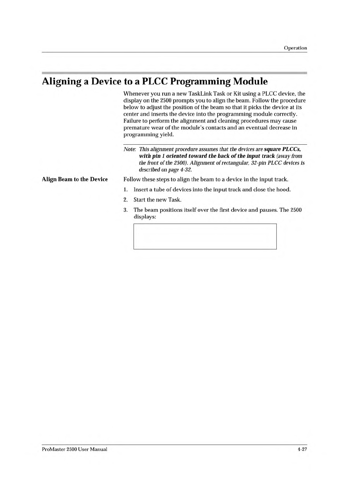
3.
The
beam
positions
itself
over
the
first
device
and
pauses.
The
2500
displays:
ProMaster
2500
User
Manual
4-27