2500_Users_Manual-.pdf - 第132页
↑ ↓ In Progress Waiting For Devices Operation 3. If the device was too close to the front of the programming module, press on the 2500's keyboard once or twice. If the device was too close to the back of the program…
PROGRAM/TEST ONLY
USE ARROW KEYS TO ALIGN BEAM WITH
DEVICE CENTER. PRESS [D] TO LOWER BEAM.
PRESS START TO CONTINUE.
1945-2
Operation
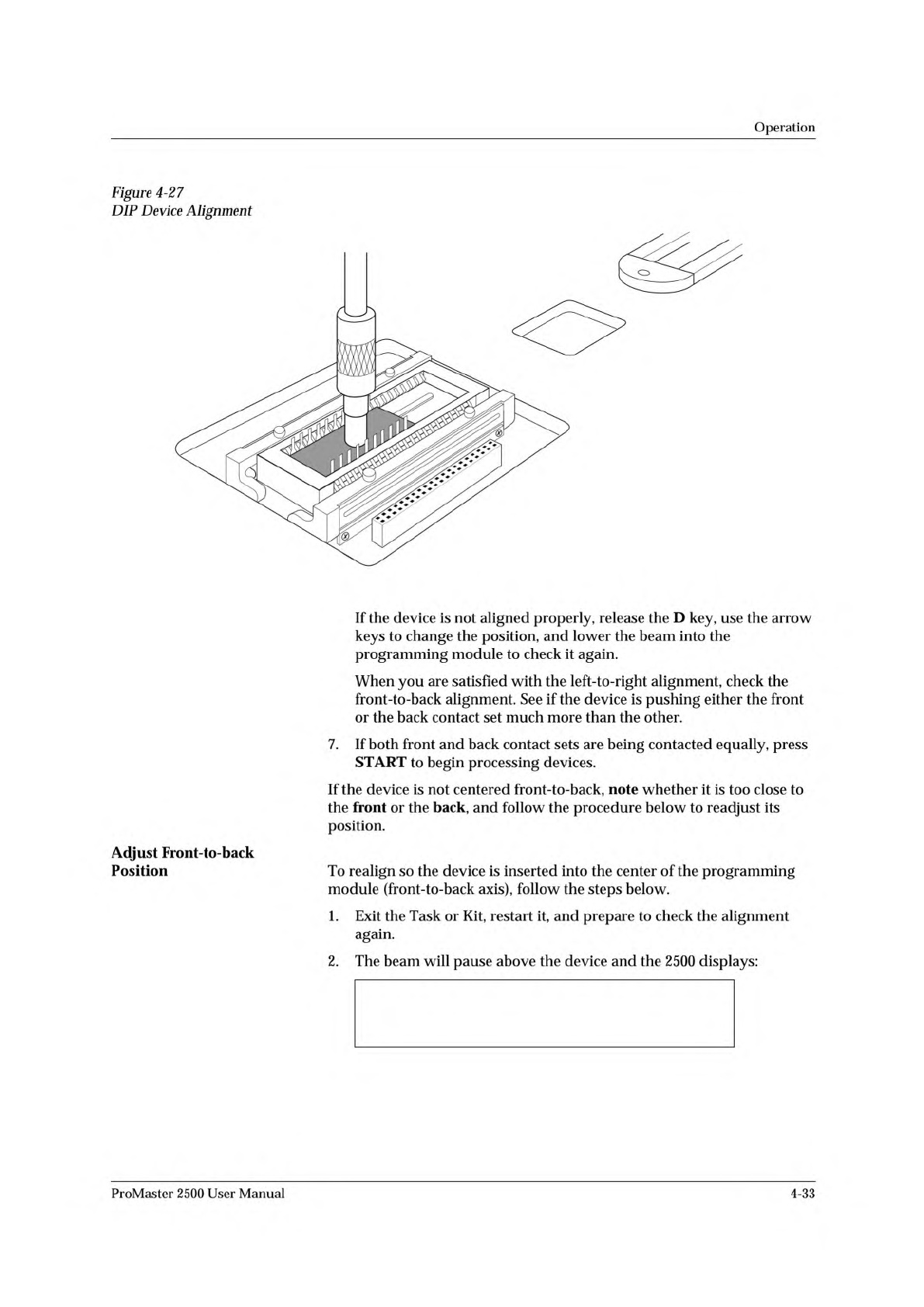
Figure
4-27
DIP
Device
Alignment
Adjust
Front-to-back
Position
If
the
device
is
not
aligned
properly,
release
the
D
key,
use
the
arrow
keys
to
change
the
position,
and
lower
the
beam
into
the
programming
module
to
check
it
again.
When
you
are
satisfied
with
the
left-to-right
alignment,
check
the
front-to-back
alignment.
See
if
the
device
is
pushing
either
the
front
or
the
back
contact
set
much
more
than
the
other.
7.
If
both
front
and
back
contact
sets
are
being
contacted
equally,
press
START
to
begin
processing
devices.
If
the
device
is
not
centered
front-to-back,
note
whether
it
is
too
close
to
the
front
or
the
back,
and
follow
the
procedure
below
to
readjust
its
position.
To
realign
so
the
device
is
inserted
into
the
center
of
the
programming
module
(front-to-back
axis),
follow
the
steps
below.
1.
Exit
the
Task
or
Kit,
restart
it,
and
prepare
to
check
the
alignment
again.
2.
The
beam
will
pause
above
the
device
and
the
2500
displays:
ProMaster
2500
User
Manual
4-33
↑
↓
In
Progress
Waiting For Devices
Operation
3.
If
the
device
was
too
close
to
the
front
of
the
programming
module,
press
on
the
2500's
keyboard
once
or
twice.
If
the
device
was
too
close
to
the
back
of
the
programming
module,
press
once
or
twice.
4.
Press
START.
The
beam
moves
the
device
over
the
programming
module
and
stops.
5.
Press
and
hold
D
on
the
2500
keyboard
to
make
certain
that
the
device
is
equidistant
between
the
front
and
back
contact
sets.
Repeat
steps
1
through
5
until
the
device
moves
into
the
center
of
the
programming
module
and
is
not
closer
to
one
side
of
the
contacts
than
the
other.
6.
When
the
alignment
is
correct,
press
START
to
continue
running
the
Task.
System
Status
Box
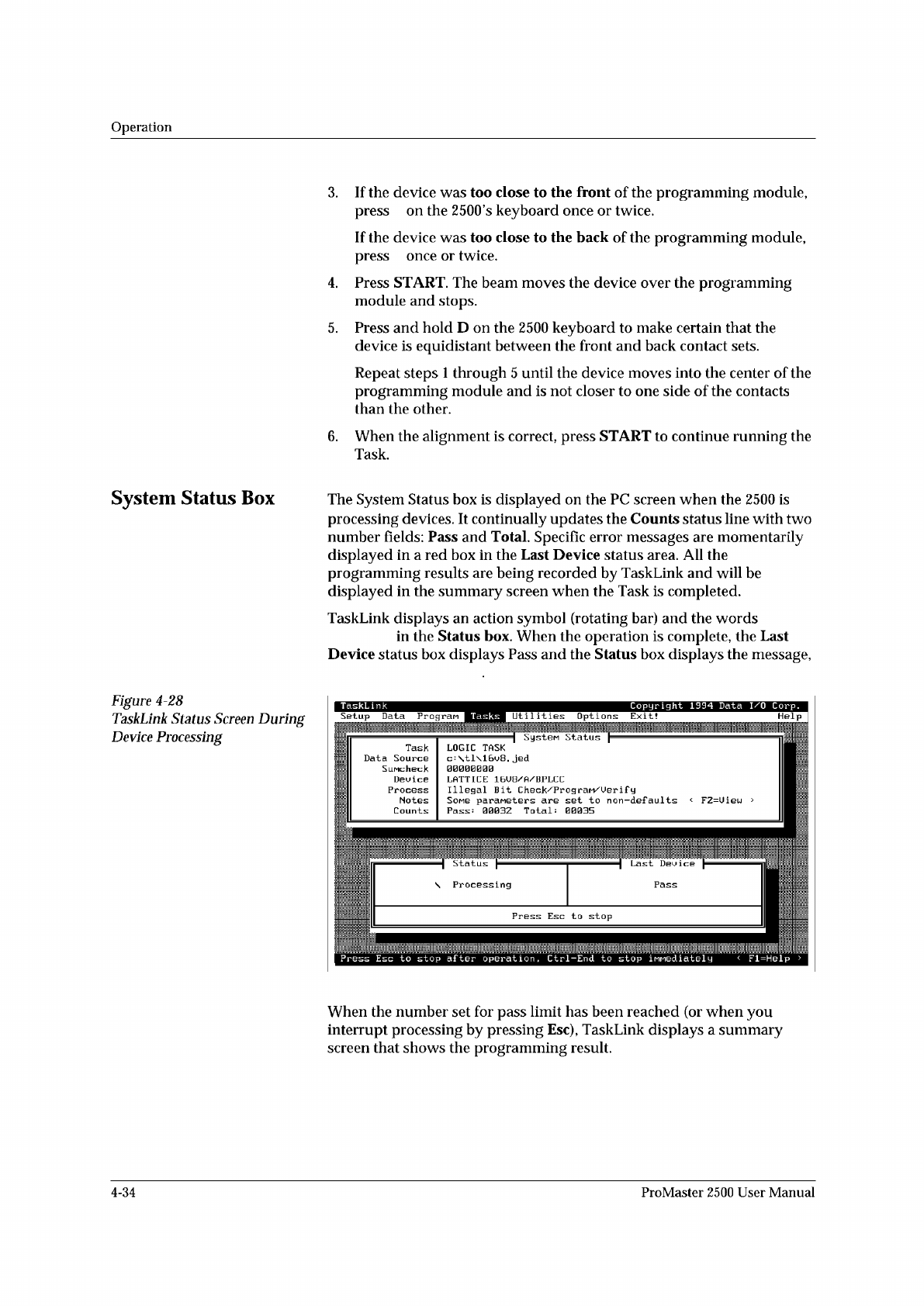
The
System
Status
box
is
displayed
on
the
PC
screen
when
the
2500
is
processing
devices.
It
continually
updates
the
Counts
status
line
with
two
number
fields:
Pass
and
Total.
Specific
error
messages
are
momentarily
displayed
in
a
red
box
in
the
Last
Device
status
area.
All
the
programming
results
are
being
recorded
by
TaskLink
and
will
be
displayed
in
the
summary
screen
when
the
Task
is
completed.
TaskLink
displays
an
action
symbol
(rotating
bar)
and
the
words
in
the
Status
box.
When
the
operation
is
complete,
the
Last
Device
status
box
displays
Pass
and
the
Status
box
displays
the
message,
Figure
4-28
TaskLink
Status
Screen
During
Device
Processing
Help
I
Status
、
Processing
TaskLink
Copyright
1994
Data
I/O
Corp.
Tasks
Util
it
les
Options
Exit!
Setup
Data
Progran
Task
Data
Source
SiiMcheck
Dau
i
ca
Process
Notes
Counts
SysteM
Status
LOGIC
TASK
c=
\tl\16u8.
jed
I.ATTI[:K
Illegal
Bit
Check/PrograM/Uerif
y
Somg
paraneters
are
set
to
non-defaults
<
FZ=Uiau
>
Total:
00035
Pass
:
0003Z
Press
Esc
to
stop
after
operation
,
Ctrl-End
to
stop
iMMediately
<
Fl=Help
>
When
the
number
set
for
pass
limit
has
been
reached
(or
when
you
interrupt
processing
by
pressing
Esc),
TaskLink
displays
a
summary
screen
that
shows
the
programming
result.
4-34
ProMaster
2500
User
Manual
1851-2
D
PRESS BEARINGS
PLATEN
APPLICATION PLATE
E
LABEL REEL COVER
F
B
C
A
G
Operation
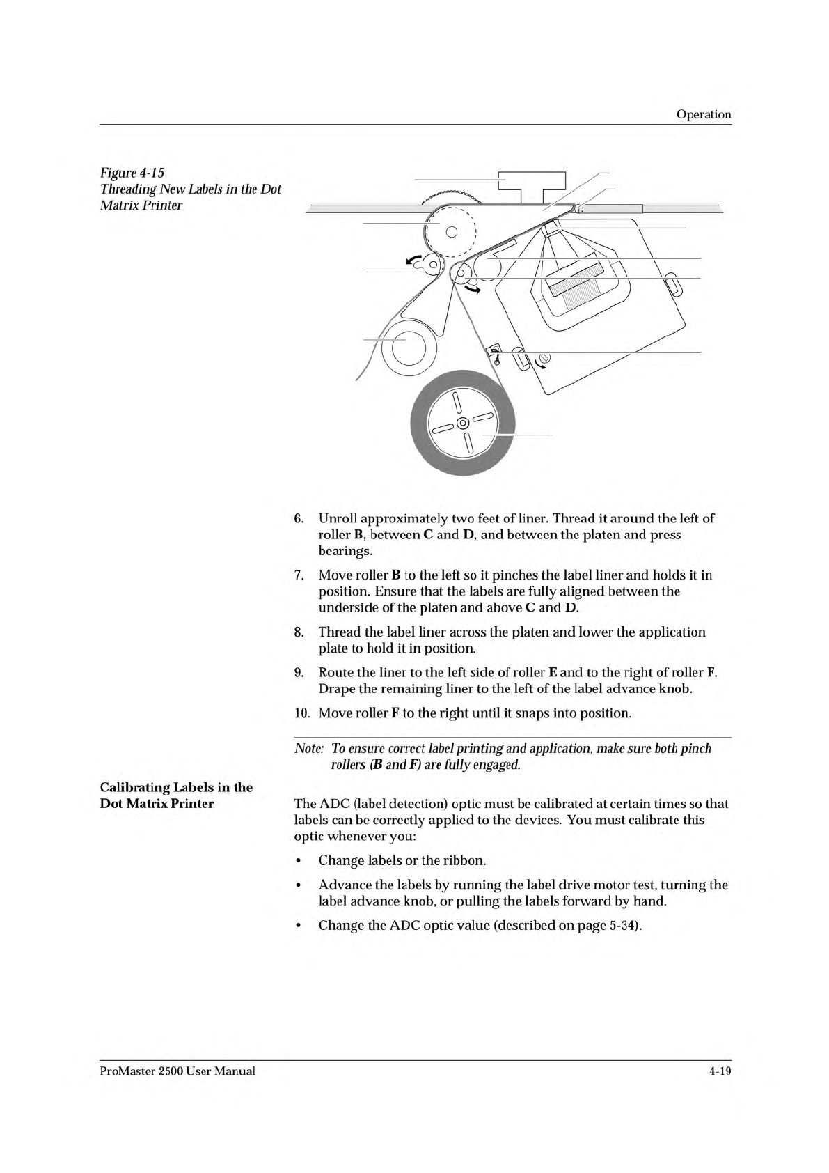
Figure
4-15
Threading
New
Labels
in
the
Dot
Matrix
Printer
Calibrating
Labels
in
the
Dot
Matrix
Printer
6.
Unroll
approximately
two
feet
of
liner.
Thread
it
around
the
left
of
roller
B,
between
C
and
D,
and
between
the
platen
and
press
bearings.
7.
Move
roller
B
to
the
left
so
it
pinches
the
label
liner
and
holds
it
in
position.
Ensure
that
the
labels
are
fully
aligned
between
the
underside
of
the
platen
and
above
C
and
D.
8.
Thread
the
label
liner
across
the
platen
and
lower
the
application
plate
to
hold
it
in
position.
9.
Route
the
liner
to
the
left
side
of
roller
E
and
to
the
right
of
roller
F.
Drape
the
remaining
liner
to
the
left
of
the
label
advance
knob.
10.
Move
roller
F
to
the
right
until
it
snaps
into
position.
Note:
To
ensure
correct
label
printing
and
application,
make
sure
both
pinch
rollers
(B
and
F)
are
fully
engaged.
The
ADC
(label
detection)
optic
must
be
calibrated
at
certain
times
so
that
labels
can
be
correctly
applied
to
the
devices.
You
must
calibrate
this
optic
whenever
you:
•
Change
labels
or
the
ribbon.
•
Advance
the
labels
by
running
the
label
drive
motor
test,
turning
the
label
advance
knob,
or
pulling
the
labels
forward
by
hand.
•
Change
the
ADC
optic
value
(described
on
page
5-34).
ProMaster
2500
User
Manual
4-19