2500_Users_Manual-.pdf - 第137页
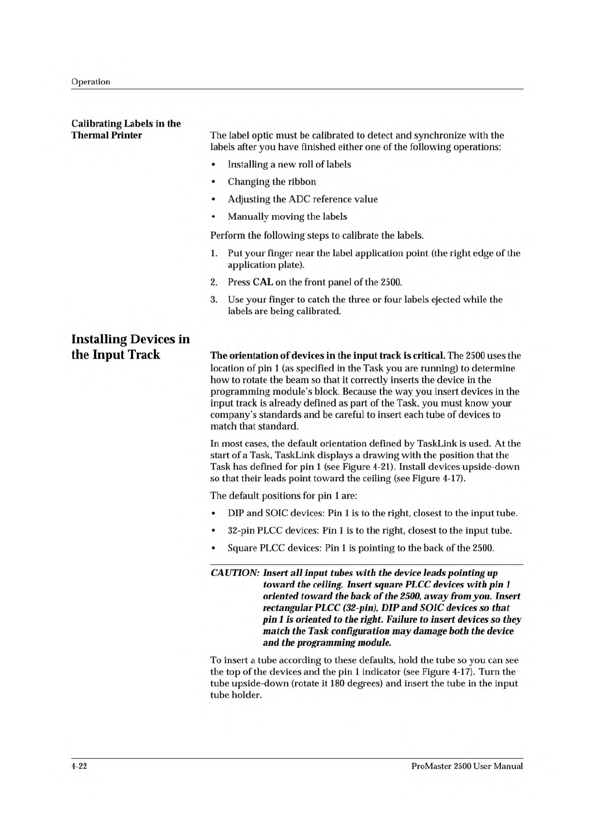
1854-3 NOTCHED CORNER INPUT TUBE HOLDER INPUT TUBE HOLDER TUBE INSERTED WITH DEVICE CONTACTS FACING UP TUBE INSERTED WITH DEVICE CONTACTS FACING UP SQUARE PLCC DEVICES DIP/SOIC DEVICES PIN 1 PIN 1 Figure 4-17 Installing …
Operation
Calibrating
Labels
in
the
Thermal
Printer
The
label
optic
must
be
calibrated
to
detect
and
synchronize
with
the
labels
after
you
have
finished
either
one
of
the
following
operations:
•
Installing
a
new
roll
of
labels
•
Changing
the
ribbon
•
Adjusting
the
ADC
reference
value
•
Manually
moving
the
labels
Perform
the
following
steps
to
calibrate
the
labels.
1.
Put
your
finger
near
the
label
application
point
(the
right
edge
of
the
application
plate).
2.
Press
CAL
on
the
front
panel
of
the
2500.
3.
Use
your
finger
to
catch
the
three
or
four
labels
ejected
while
the
labels
are
being
calibrated.
Installing
Devices
in
the
Input
Track
The
orientation
of
devices
in
the
input
track
is
critical.
The
2500
uses
the
location
of
pin
1
(as
specified
in
the
Task
you
are
running)
to
determine
how
to
rotate
the
beam
so
that
it
correctly
inserts
the
device
in
the
programming
module's
block.
Because
the
way
you
insert
devices
in
the
input
track
is
already
defined
as
part
of
the
Task,
you
must
know
your
company's
standards
and
be
careful
to
insert
each
tube
of
devices
to
match
that
standard.
In
most
cases,
the
default
orientation
defined
by
TaskLink
is
used.
At
the
start
of
a
Task,
TaskLink
displays
a
drawing
with
the
position
that
the
Task
has
defined
for
pin
1
(see
Figure
4-21).
Install
devices
upside-down
so
that
their
leads
point
toward
the
ceiling
(see
Figure
4-17).
The
default
positions
for
pin
1
are:
•
DIP
and
SOIC
devices:
Pin
1
is
to
the
right,
closest
to
the
input
tube.
•
32-pin
PLCC
devices:
Pin
1
is
to
the
right,
closest
to
the
input
tube.
•
Square
PLCC
devices:
Pin
1
is
pointing
to
the
back
of
the
2500.
CAUTION:
Insert
input
tubes
with
the
device
leads
pointing
up
toward
the
ceiling.
Insert
square
PLCC
devices
with
pin
1
oriented
toward
the
back
of
the
2500,
away
from
you.
Insert
rectangular
PLCC
(32-pin),
DIP
and
SOIC
devices
so
that
pin
1
is
oriented
to
the
right.
Failure
to
insert
devices
so
they
match
the
Task
configuration
may
damage
both
the
device
and
the
programming
module.
To
insert
a
tube
according
to
these
defaults,
hold
the
tube
so
you
can
see
the
top
of
the
devices
and
the
pin
1
indicator
(see
Figure
4-17).
Turn
the
tube
upside-down
(rotate
it
180
degrees)
and
insert
the
tube
in
the
input
tube
holder.
4-22
ProMaster
2500
User
Manual
1854-3
NOTCHED
CORNER
INPUT TUBE
HOLDER
INPUT TUBE
HOLDER
TUBE INSERTED
WITH DEVICE
CONTACTS
FACING UP
TUBE INSERTED
WITH DEVICE
CONTACTS
FACING UP
SQUARE
PLCC
DEVICES
DIP/SOIC
DEVICES
PIN 1
PIN 1
Figure
4-17
Installing
Devices
in
the
Tu
加
Holder
Operation
Running
a
Task
Start
TaskLink
at
the
DOS
prompt
in
the
directory
where
TaskLink
is
installed.
Type:
tl
After
a
few
seconds,
the
Run
Task/Kit
list
box
appears
(similar
to
the
one
shown
in
Figure
4-2).
A
Kit
is
a
special
collection
of
Tasks,
which
will
be
explained
later
in
this
chapter.
For
now,
ignore
all
references
to
Kits.
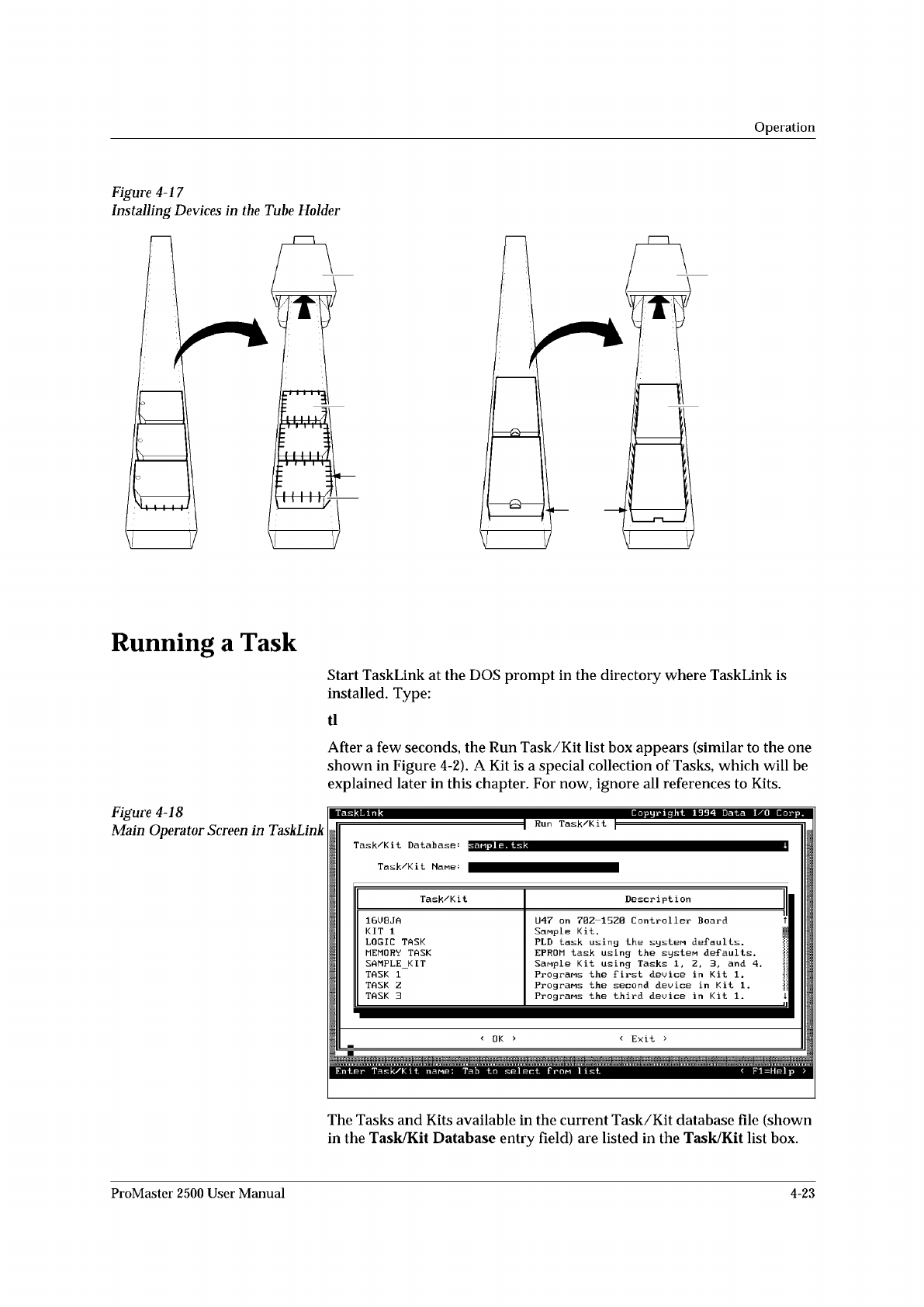
Figure
4-18
Main
Operator
Screen
in
TaskLink
The
Tasks
and
Kits
available
in
the
current
Task/Kit
database
file
(shown
in
the
Task/Kit
Database
entry
field)
are
listed
in
the
Task/Kit
list
box.
ProMaster
2500
User
Manual
4-23
↑ ↓
↵
↵
↵
↑ ↓ ↵
Operation
Selecting
a
Task
Selecting
a
Database
File
Select
Process
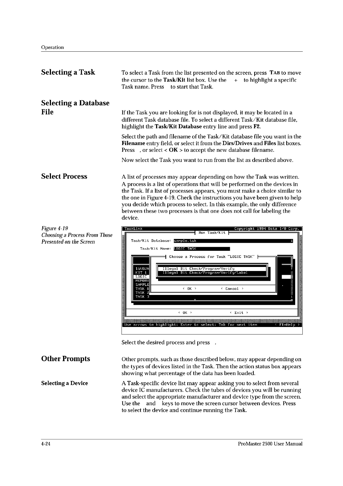
Figure
4-19
Choosing
a
Process
From
Those
Presented
on
the
Screen
Other
Prompts
Selecting
a
Device
To
select
a
Task
from
the
list
presented
on
the
screen,
press
Tab
to
move
the
cursor
to
the
Task/Kit
list
box.
Use
the
+
to
highlight
a
specific
Task
name.
Press
to
start
that
Task.
If
the
Task
you
are
looking
for
is
not
displayed,
it
may
be
located
in
a
different
Task
database
file.
To
select
a
different
Task/Kit
database
file,
highlight
the
Task/Kit
Database
entry
line
and
press
F2.
Select
the
path
and
filename
of
the
Task/Kit
database
file
you
want
in
the
Filename
entry
field,
or
select
it
from
the
Dirs/Drives
and
Files
list
boxes.
Press
,
or
select
<
OK
>
to
accept
the
new
database
filename.
Now
select
the
Task
you
want
to
run
from
the
list
as
described
above.
A
list
of
processes
may
appear
depending
on
how
the
Task
was
written.
A
process
is
a
list
of
operations
that
will
be
performed
on
the
devices
in
the
Task.
If
a
list
of
processes
appears,
you
must
make
a
choice
similar
to
the
one
in
Figure
4-19.
Check
the
instructions
you
have
been
given
to
help
you
decide
which
process
to
select.
In
this
example,
the
only
difference
between
these
two
processes
is
that
one
does
not
call
for
labeling
the
device.
Select
the
desired
process
and
press
Other
prompts,
such
as
those
described
below,
may
appear
depending
on
the
types
of
devices
listed
in
the
Task.
Then
the
action
status
box
appears
showing
what
percentage
of
the
data
has
been
loaded.
A
Task-specific
device
list
may
appear
asking
you
to
select
from
several
device
IC
manufacturers.
Check
the
tubes
of
devices
you
will
be
running
and
select
the
appropriate
manufacturer
and
device
type
from
the
screen.
Use
the
and
keys
to
move
the
screen
cursor
between
devices.
Press
to
select
the
device
and
continue
running
the
Task.
4-24
ProMaster
2500
User
Manual