2500_Users_Manual-.pdf - 第140页
Operation If you start a Task with an incorrect number in the Parts /tube field, press STOP and then LOWER CASE + T. Enter the correct number. Press ENTER and then START to continue running the Task. This screen also ind…
5
Preventive
Maintenance
This
chapter
describes
ProMaster
2500
theory
of
operation,
diagnostics,
and
preventive
maintenance
procedures.
Diagnostic
tests
are
described
for
the
motors,
solenoids,
optics,
switches,
and
programming
electronics.
The
information
in
this
chapter
is
presented
in
the
following
order:
Theory
of
Operation
5-2
Conditions
Requiring
Corrective
Action
5-21
Corrective
Adjustments
5-24
Diagnostics
5-30
Preventive
Maintenance
Procedures
For
Operators
5-55
Preventive
Maintenance
Procedures
For
Service
Technicians
5-60
WARNING:
Performing
some
of
the
diagnostic
procedures
in
this
chapter
will
expose
you
to
harmful
high
voltage.
To
avoid
electrical
shock
or
mechanical
injury,
only
a
service
technician
trained
on
electromechanical
equipment
should
perform
the
diagnostic
tests
that
require
lifting
the
main
plate
while
the
2500
is
on.
ProMaster
2500
User
Manual
5-1
Operation
If
you
start
a
Task
with
an
incorrect
number
in
the
Parts
/tube
field,
press
STOP
and
then
LOWER
CASE
+
T.
Enter
the
correct
number.
Press
ENTER
and
then
START
to
continue
running
the
Task.
This
screen
also
indicates
where
TaskLink
expects
device
pin
1
to
be
located
when
the
device
is
in
the
input
track.
This
is
critical
for
correct
device
handling
and
insertion
in
the
programming
module
socket.
Make
certain
that
your
device
matches
this
positioning.
Refer
to
page
4-22
for
more
information
on
installing
devices
in
the
input
tube
holder.
The
system
automatically
downloads
the
data
file
defined
in
your
Task
or
prompts
you
to
insert
a
master
device.
If
the
Task
asks
you
to
load
RAM
data
from
a
master
device,
TaskLink
prompts
you
to
insert
the
master
device
to
be
loaded.
Place
the
device
in
the
input
track,
against
the
programming
station
stop
guide.
Be
careful
to
observe
the
correct
orientation
of
pin
1.
Close
the
hood.
The
2500
detects
the
device,
picks
it
up,
inserts
it
in
the
programming
module,
and
loads
the
device's
data
into
RAM.
After
the
load,
the
master
device
is
set
in
the
left
device
recess
near
the
labeler.
4-26
ProMaster
2500
User
Manual
PROGRAM/TEST ONLY
USE ARROW KEYS TO ALIGN BEAM WITH
DEVICE CENTER. PRESS [D] TO LOWER BEAM.
PRESS START TO CONTINUE.
Operation
Aligning
a
Device
to
a
PLCC
Programming
Module
Whenever
you
run
a
new
TaskLink
Task
or
Kit
using
a
PLCC
device,
the
display
on
the
2500
prompts
you
to
align
the
beam.
Follow
the
procedure
below
to
adjust
the
position
of
the
beam
so
that
it
picks
the
device
at
its
center
and
inserts
the
device
into
the
programming
module
correctly.
Failure
to
perform
the
alignment
and
cleaning
procedures
may
cause
premature
wear
of
the
module's
contacts
and
an
eventual
decrease
in
programming
yield.
Note:
This
alignment
procedure
assumes
that
the
devices
are
square
PLCCsf
with
pin
1
oriented
toward
the
back
of
the
input
track
(away
from
the
front
of
the
2500).
Alignment
of
rectangular,
32-pin
PLCC
devices
is
described
on
page
4-32.
Align
Beam
to
the
Device
Follow
these
steps
to
align
the
beam
to
a
device
in
the
input
track.
1.
Insert
a
tube
of
devices
into
the
input
track
and
close
the
hood.
2.
Start
the
new
Task.
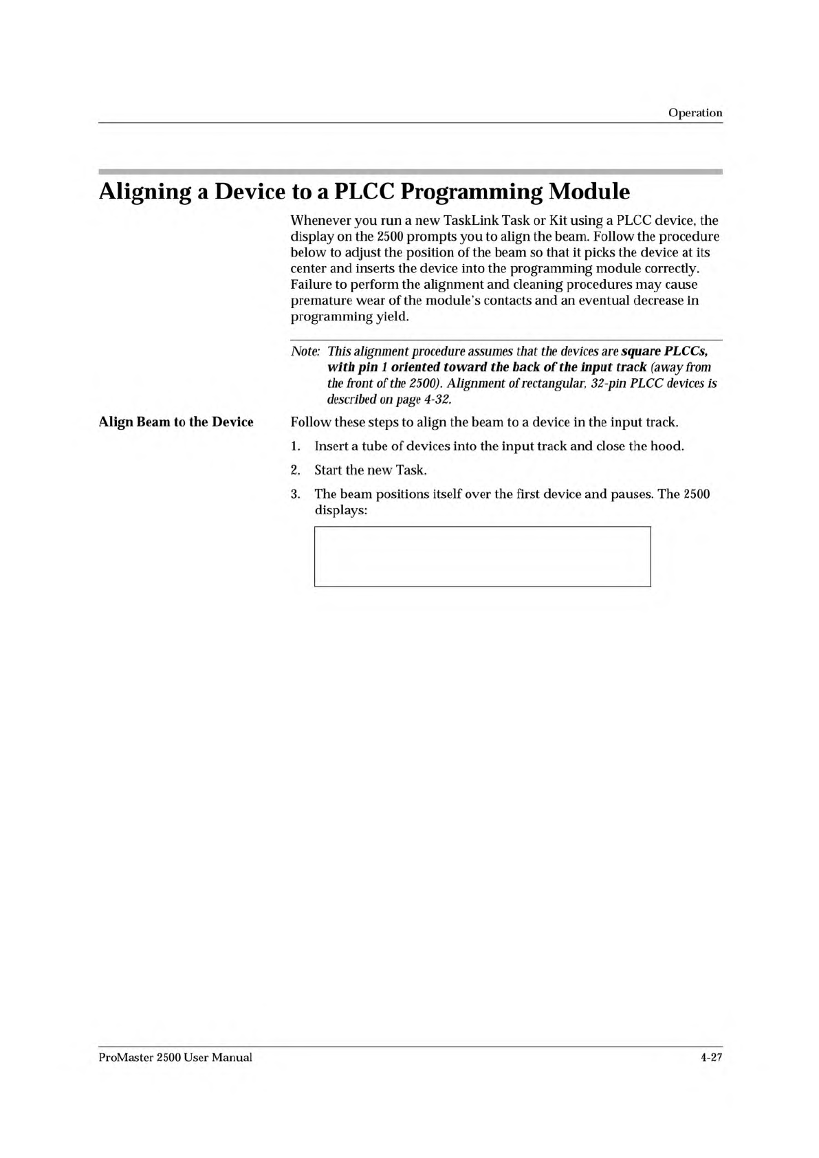
3.
The
beam
positions
itself
over
the
first
device
and
pauses.
The
2500
displays:
ProMaster
2500
User
Manual
4-27