2500_Users_Manual-.pdf - 第156页
Preventive Maintenance Theory of Operation This section describes the operation of each of the ProMaster 2500's major components. TaskLink You will normally operate the 2500 under the system control of the TaskLink …
5
Preventive
Maintenance
This
chapter
describes
ProMaster
2500
theory
of
operation,
diagnostics,
and
preventive
maintenance
procedures.
Diagnostic
tests
are
described
for
the
motors,
solenoids,
optics,
switches,
and
programming
electronics.
The
information
in
this
chapter
is
presented
in
the
following
order:
Theory
of
Operation
5-2
Conditions
Requiring
Corrective
Action
5-21
Corrective
Adjustments
5-24
Diagnostics
5-30
Preventive
Maintenance
Procedures
For
Operators
5-55
Preventive
Maintenance
Procedures
For
Service
Technicians
5-60
WARNING:
Performing
some
of
the
diagnostic
procedures
in
this
chapter
will
expose
you
to
harmful
high
voltage.
To
avoid
electrical
shock
or
mechanical
injury,
only
a
service
technician
trained
on
electromechanical
equipment
should
perform
the
diagnostic
tests
that
require
lifting
the
main
plate
while
the
2500
is
on.
ProMaster
2500
User
Manual
5-1
Preventive
Maintenance
Theory
of
Operation
This
section
describes
the
operation
of
each
of
the
ProMaster
2500's
major
components.
TaskLink
You
will
normally
operate
the
2500
under
the
system
control
of
the
TaskLink
software
program,
running
on
a
personal
computer
(PC).
TaskLink
uses
a
set
of
computer
remote
control
commands
to
communicate
with
the
2500.
These
commands
control
the
programming,
handling,
labeling,
and
binning
operations
of
the
2500.
During
a
typical
communication
sequence
between
TaskLink
and
the
2500,
TaskLink
issues
a
command
to
a
subsystem,
then
yields
control
to
that
subsystem
and
waits
for
a
reply.
The
communication
sequence
will
usually
occur
in
the
following
manner:
1.
TaskLink
sends
a
program
command
to
the
Programming
Electronics
(PE)
subsystem
and
waits
for
the
PE
to
complete
the
procedure.
2.
When
the
PE
has
completed
the
procedure,
it
sends
a
signal
to
TaskLink
indicating
whether
the
device
has
passed
or
failed.
3.
If
the
device
passed,
TaskLink
looks
at
the
task
to
determine
what
additional
procedures
need
to
be
performed.
TaskLink
then
sends
the
next
command
to
the
2500.
If
the
device
failed,
TaskLink
displays
an
error
message
on
your
PC
monitor.
If
the
error
is
related
to
device
testing
or
programming,
the
error
code
is
recorded
in
a
log
file
on
the
hard
disk
of
your
PC.
Error
messages
are
described
in
Chapter
6.
4.
When
a
device
passes
the
programming/
verify
operation,
TaskLink
receives
a
category
signal
from
the
programming
electronics,
and
sends
it
to
the
2500.
The
2500
checks
the
signal
against
the
bin
map
and
processes
the
device
accordingly.
Device
Processing
This
section
describes
the
flow
of
a
device
through
the
2500.
A
device
travels
from
the
input
tube
to
the
programming
station,
then
to
the
labeling
station
(if
the
device
passes
the
verification
tests),
and
then
to
one
of
two
output
tubes.
Device
Moves
to
Programming
Station
A
device
travels
from
the
input
tube
to
the
programming
station
in
the
following
manner:
1.
When
TaskLink
runs
a
task,
it
prompts
the
handler
to
perform
a
brief
self-calibration
initializing
routine
before
loading
the
first
device.
One
of
the
checks
performed
during
this
routine
is
to
see
if
the
hood
is
raised.
If
the
hood
is
raised,
the
handler
displays
a
warning
message
prompting
the
operator
to
lower
the
hood
before
continuing
the
task.
2.
The
operator
inserts
a
tube
containing
blank
(unprogrammed)
devices
into
the
input
tube
holder.
This
action
is
detected
by
the
input
tube
holder
microswitches
(19
in
Figure
5-3).
5-2
ProMaster
2500
User
Manual
1939-1
1
15 (Under main plate)
2
17
3
4
13
14
20 (Output tube 1)
21 (Output tube 2)
19
11
12
16 (Under main plate)
22
23
Preventive
Maintenance
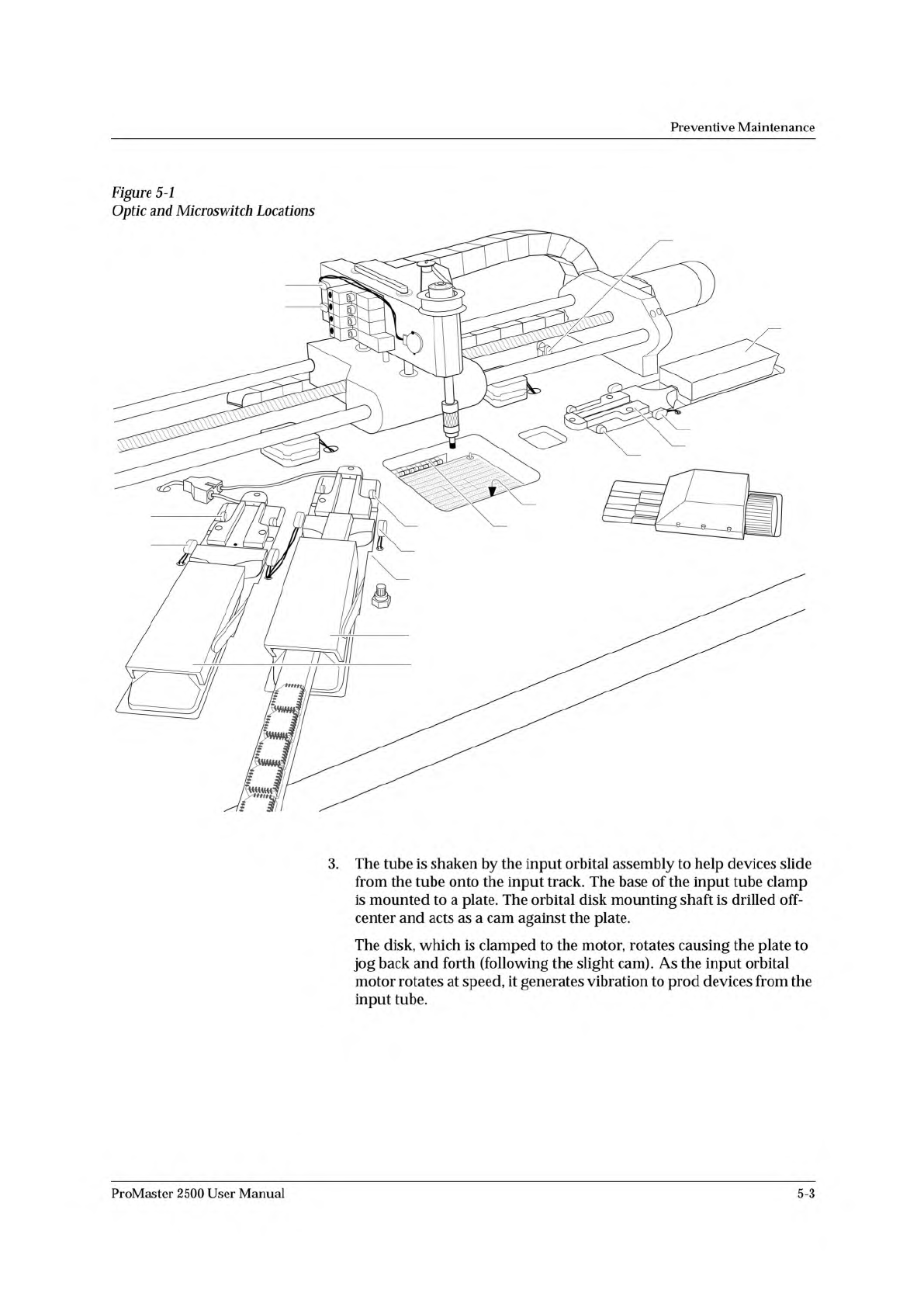
Figure
5-1
Optic
and
Microswitch
Locations
3.
The
tube
is
shaken
by
the
input
orbital
assembly
to
help
devices
slide
from
the
tube
onto
the
input
track.
The
base
of
the
input
tube
clamp
is
mounted
to
a
plate.
The
orbital
disk
mounting
shaft
is
drilled
off-
center
and
acts
as
a
cam
against
the
plate.
The
disk,
which
is
clamped
to
the
motor,
rotates
causing
the
plate
to
jog
back
and
forth
(following
the
slight
cam).
As
the
input
orbital
motor
rotates
at
speed,
it
generates
vibration
to
prod
devices
from
the
input
tube.
ProMaster
2500
User
Manual
5-3