2500_Users_Manual-.pdf - 第158页
CONTINUITY TEST FAIL CONTINUITY TEST FAIL Preventive Maintenance Device Is Inserted into Programming Module Device Is Programmed 4. A device, positioned against the programming station stop guide, blocks the beam of the …
1939-1
1
15 (Under main plate)
2
17
3
4
13
14
20 (Output tube 1)
21 (Output tube 2)
19
11
12
16 (Under main plate)
22
23
Preventive
Maintenance
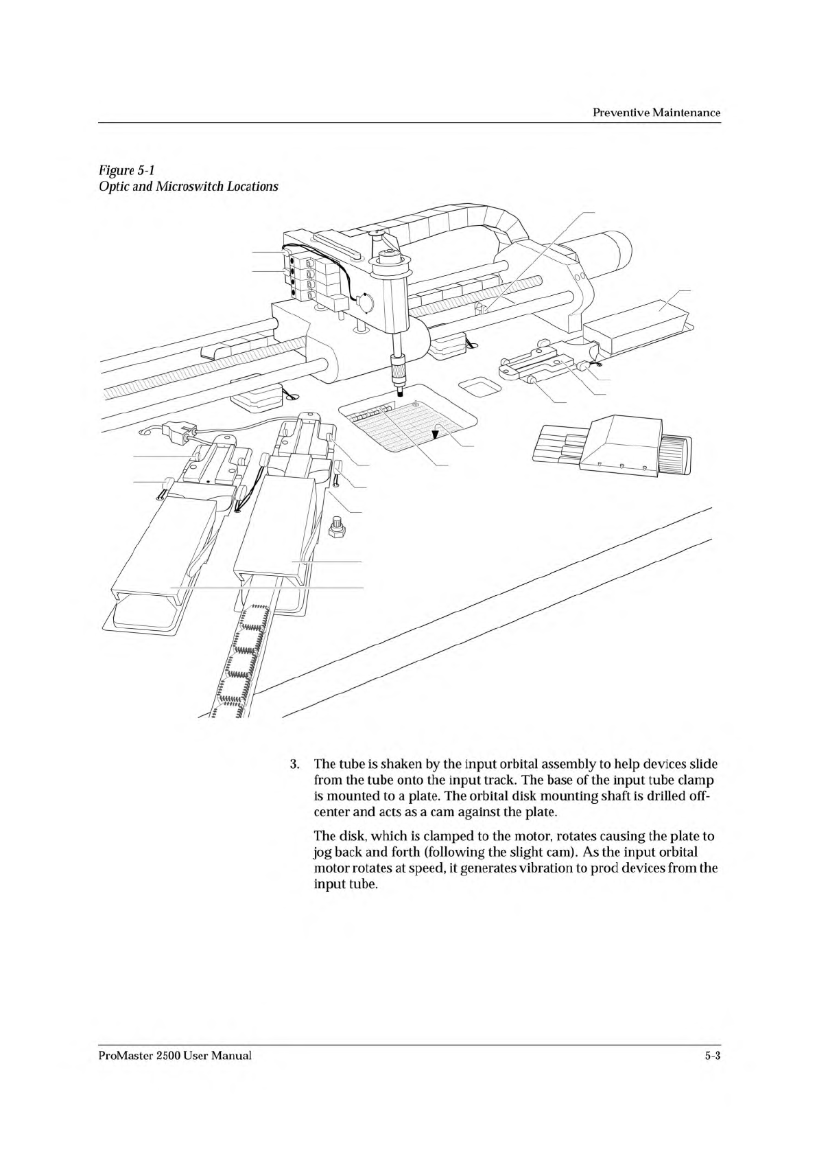
Figure
5-1
Optic
and
Microswitch
Locations
3.
The
tube
is
shaken
by
the
input
orbital
assembly
to
help
devices
slide
from
the
tube
onto
the
input
track.
The
base
of
the
input
tube
clamp
is
mounted
to
a
plate.
The
orbital
disk
mounting
shaft
is
drilled
off-
center
and
acts
as
a
cam
against
the
plate.
The
disk,
which
is
clamped
to
the
motor,
rotates
causing
the
plate
to
jog
back
and
forth
(following
the
slight
cam).
As
the
input
orbital
motor
rotates
at
speed,
it
generates
vibration
to
prod
devices
from
the
input
tube.
ProMaster
2500
User
Manual
5-3
CONTINUITY TEST FAIL
CONTINUITY TEST
FAIL
Preventive
Maintenance
Device
Is
Inserted
into
Programming
Module
Device
Is
Programmed
4.
A
device,
positioned
against
the
programming
station
stop
guide,
blocks
the
beam
of
the
part
detect
optic.
The
handler
detects
the
blocked
optic
and
advances
the
beam
until
it
is
centered
over
the
device
(the
location
is
determined
by
the
pre-defined
package
size
downloaded
by
TaskLink).
The
handler's
firmware
stores
the
package
dimensions
for
all
supported
package
types.
The
firmware
prompts
the
operator
to
align
the
first
device
in
a
run.
The
beam's
traverse
motor
advances
the
number
of
motor
steps
necessary
to
align
the
chuck
over
the
center
of
the
waiting
device.
5.
The
beam
up/down
solenoid
(solenoid
test
4
in
Figure
5-16)
switches
on
the
low
pressure
air
to
lower
the
beam.
The
beam
down
optic
(3
in
Figure
5-1),
mounted
on
the
side
of
the
beam,
senses
the
vertical
position
of
the
beam
and
triggers
the
high
pressure
solenoid
to
complete
the
lowering
of
the
beam
to
the
device.
The
rubber
chuck
tip
creates
a
vacuum
seal
on
the
device.
When
the
vacuum
seal
has
been
created,
a
switch
on
the
left
side
of
the
beam
is
triggered.
The
2500
detects
the
vacuum
and
the
beam
picks
up
the
device.
The
beam
rises
with
the
device
on
its
tip,
moves
to
the
programming
station,
pauses
so
that
the
operator
can
align
the
first
device
in
a
run,
and
lowers
the
device
into
the
programming
module.
Before
the
device
is
programmed,
TaskLink
and
the
PE
perform
several
device
tests.
Each
device-related
operation
performed
by
the
PE
is
part
of
a
programming
algorithm
specified
by
the
device
manufacturer.
In
most
cases
these
specifications
instruct
the
PE
to
perform
the
following
procedures:
1.
A
pre-programming
check
of
the
device
2.
The
programming
of
the
device
3.
A
post-programming
data
verification
cycle
A
typical
pre-programming
sequence
includes
the
following
steps:
•
Check
for
presence
of
a
device
in
the
programming
module
—
This
verifies
that
a
device
is
in
the
programming
block.
•
Continuity
test
—
This
confirms
that
the
device
pins
have
continuity
with
the
module's
contacts.
Dirty
module
contacts
or
a
misaligned
device
can
cause
the
handler
to
fail
this
test.
In
case
of
failure,
TaskLink
displays
and
records
the
test
result
in
the
log
file.
•
Check
for
misjustified
device
—
This
confirms
that
the
device
ground
and
VCC
pins
match
the
programming
module's
ground
and
VCC.
(Refer
to
the
device
alignment
procedure,
beginning
on
page
4-22.)
This
test
also
detects
devices
that
have
been
installed
backwards.
When
this
test
fails,
TaskLink
displays
5-4
ProMaster
2500
User
Manual
SECURITY FUSE VIOLATION
ELECTRONIC ID ERROR
NON-BLANK
ILLEGAL BIT
PROGRAM FAIL
Preventive
Maintenance
•
Security
fuse
check
—
Some
devices
have
a
security
fuse
feature
that,
when
programmed,
prevents
the
reading
of
the
main
fuse
pattern.
Some
semiconductor
manufacturers
allow
the
programmer
to
check
the
fuse
before
trying
to
program
the
fuses
in
the
main
array.
If
the
security
fuse
is
blown,
the
device
cannot
be
read
or
programmed
and
TaskLink
displays
.
•
Check
silicon
ID
—
Many
devices
have
internal
identification
numbers
(an
electronic
I.D.)
that
the
PE
can
read.
These
numbers
allow
the
PE
to
determine
the
manufacturer
of
the
device,
the
part
number,
and
the
type.
For
example,
if
the
Task
identifies
a
device
from
manufacturer
A
(requiring
a
specific
programming
algorithm)
and
a
tube
of
devices
from
manufacturer
B
(requiring
a
different
programming
algorithm)
is
mistakenly
inserted,
TaskLink
displays
and
the
handler
routes
these
devices
to
an
output
tube
specified
in
the
Task
setup
before
a
programming
pulse
has
been
applied.
•
Blank
check
—
This
checks
to
ensure
that
all
the
fuses
in
the
device's
main
array
are
blank
(unprogrammed)
.
Most
devices
allow
the
programming
cycle
to
continue
even
when
a
programmed
fuse
has
been
detected.
If
the
Task
is
configured
to
reject
devices
with
any
programmed
fuses,
TaskLink
displays
and
the
handler
routes
these
devices
to
an
output
tube
specified
in
the
Task
setup.
•
Illegal
bit
check
—
Some
devices
that
are
programmable
by
the
system
are
not
electrically
erasable.
The
PE
can
erase
only
electrically
erasable
devices.
The
PE
checks
each
fuse
to
make
sure
the
fuse
is
unprogrammed
(blank).
If
the
PE
finds
a
programmed
fuse
in
the
device
and
its
RAM
data
indicates
that
the
fuse
should
be
unprogrammed,
TaskLink
displays
.
Most
erasable/
programmable
devices
cannot
be
erased
in
the
socket.
The
system
routes
these
devices
to
an
output
tube
specified
in
the
binning
setup.
If
the
device
passes
all
these
pre-programming
tests,
the
PE
begins
programming,
using
the
manufacturer's
programming
algorithm.
Some
algorithms
require
that
the
PE
apply
a
single
programming
pulse
to
the
fuse,
and
then
immediately
check
the
fuse
to
see
if
it's
programmed
before
continuing.
This
type
of
algorithm
normally
specifies
a
maximum
number
of
times
that
the
PE
can
try
to
program
a
fuse.
If
the
fuse
fails
to
program
after
the
maximum
number
of
pulses
have
been
applied,
TaskLink
fails
the
device
and
displays
.
ProMaster
2500
User
Manual
5-5