2500_Users_Manual-.pdf - 第163页
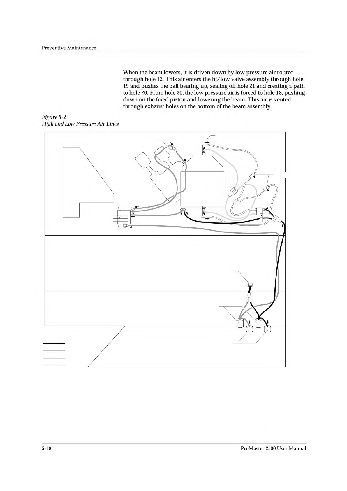
Preventive Maintenance System Air Flow Air enters the 2500 through a 1/4-inch air connector on the rear and branches through a Y connection to the low and high air pressure regulators (see Figure 5-2). The air exits each…
Preventive
Maintenance
The
beam
has
a
traverse
motor
(with
an
encoder)
that
moves
the
beam
along
the
lead
screw
in
its
horizontal
(left-to-right)
travel.
The
encoder
counts
the
number
of
steps
the
beam
travels
from
the
home
position
and
sends
that
information
to
the
main
board.
The
beam
assembly
also
has
a
beam
rotate
motor
that
controls
the
rotation
of
the
device
on
the
chuck.
The
2500
has
three
additional
stepper
motors.
The
label
drive
motor
(used
in
the
dot
matrix
printer
and
in
the
thermal
printer)
advances
labels
at
a
precise
rate
past
the
print
head
to
create
even
spacing
between
characters.
This
motor
also
advances
the
liner
so
the
label
contacts
the
device
according
to
the
position
defined
by
the
label
placement
value
specified
in
the
Task.
The
input
orbital
motor
rotates,
causing
the
input
orbital
assembly
to
shake.
This
shaking
helps
the
devices
slide
from
the
input
tube
to
the
input
track.
The
output
orbital
motor
performs
a
similar
function
when
devices
are
sliding
from
the
output
track
to
the
output
tubes.
Solenoids
The
handler
uses
air
solenoids
that
are
activated
by
signals
from
MOSFET
circuitry
on
the
controller
board.
When
the
correct
logic
drive
signal
for
a
specific
solenoid
is
active,
an
LED
associated
with
that
circuit
is
lit.
Beam
and
Chucks
The
microprocessor-controlled
beam,
using
a
pick-and-place
head
and
an
interchangeable
vacuum
chuck,
picks
up
and
places
devices
at
the
programming
or
labeling
station
and
releases
devices
into
the
output
track.
The
beam
traverse
stepper
motor
drives
the
beam
on
the
horizontal
(left-
to-right)
axis
along
the
lead
screw.
You
must
keep
this
lead
screw
clean
and
lightly
lubricated
to
ensure
correct
beam
operation.
If
you
do
not
keep
the
lead
screw
clean,
the
beam
may
eventually
develop
alignment
problems
and
fail
to
locate
the
center
of
a
device.
Beam
stalling
is
a
term
used
to
describe
the
failure
of
the
beam
to
travel
freely
on
the
lead
screw,
resulting
in
lost
steps
and
the
inability
to
travel
the
full
distance
of
the
lead
screw.
The
chance
of
this
occurring
is
very
low,
because
the
beam
traverse
motor
has
an
encoder
that
keeps
track
of
the
beam's
movement.
A
device
rotate
motor,
which
is
mounted
on
the
beam
assembly,
is
connected
to
the
beam
head
by
a
timing
belt.
The
device
rotate
motor
controls
the
rotation
of
devices
on
the
chuck
so
that
the
device
orientation
can
be
adjusted
for
programming
or
labeling.
5-8
ProMaster
2500
User
Manual
Preventive
Maintenance
System
Air
Flow
Air
enters
the
2500
through
a
1/4-inch
air
connector
on
the
rear
and
branches
through
a
Y
connection
to
the
low
and
high
air
pressure
regulators
(see
Figure
5-2).
The
air
exits
each
regulator
in
two
ways:
to
the
gauge
(to
display
the
PSI)
and
through
the
2500
as
described
below.
Low
air
pressure
should
be
set
to
30
PSI,
and
high
air
pressure
should
be
set
to
85
PSI.
Solenoids
switch
high
or
low
air
pressure
to
the
beam
to
perform
various
functions,
as
shown
in
the
table
and
as
described
in
the
following
sections.
High
Pressure
Low
Pressure
Beam
vacuum
generators
Lower
beam
to
pick
up
device
Lower
beam
to
release
device
Final
insertion
force
into
Initial
insertion
force
into
programming
programming
module module
Programming
module
Device
blow
off
clamps
Output
tube
air
to
start
device
movement
Low
Air
Pressure
Low
pressure
air
is
routed
from
the
low
pressure
regulator
to
a
solenoid
block
where
it
is
switched
to
either
the
beam
or
the
output
track
(see
Figure
5-2).
Beam
Up/down
This
section
describes
how
the
air
pressure
is
routed
through
channels
inside
the
beam.
Refer
to
Figure
5-16
for
the
location
of
the
beam
solenoids
and
Figure
5-3
for
the
location
of
air
channels
as
you
read
this
section.
After
the
2500
powers
up,
solenoid
4
(beam
up/down)
forces
low
pressure
air
through
an
air
channel
in
the
beam
baffle
plate
from
hole
1
1
to
hole
10,
up
through
the
beam
to
hole
16
and
hole
17,
and
finally
to
the
top
of
the
fixed
piston,
pushing
the
beam
assembly
up
into
the
ready
position.
Low
pressure
air
passes
through
the
beam
and
a
single
air
cap
(cavity),
which
dampens
out
air
spikes
and
is
routed
directly
to
solenoids
4
and
5.
ProMaster
2500
User
Manual
5-9
2054-2
MAIN PLATE (Underside)
BACK OF BASE
BOTTOM OF BASE
FRONT OF BASE
BLACK (HP)
GRAY (LP)
BLUE
RED
EXTERNAL INPUT
REGULATORS
GAUGES
REGULATORS
AIR CYLINDER (1 of 2)
BLOW REGULATOR
SOLENOID 8
TO BEAM
SOLENOIDS
2 AND 3
TO OUTPUT TUBE
PART BLOW IN
HIGH
LOW
Preventive
Maintenance
When
the
beam
lowers,
it
is
driven
down
by
low
pressure
air
routed
through
hole
12.
This
air
enters
the
hi/low
valve
assembly
through
hole
19
and
pushes
the
ball
bearing
up,
sealing
off
hole
21
and
creating
a
path
to
hole
20.
From
hole
20,
the
low
pressure
air
is
forced
to
hole
18,
pushing
down
on
the
fixed
piston
and
lowering
the
beam.
This
air
is
vented
through
exhaust
holes
on
the
bottom
of
the
beam
assembly.
Figure
5-2
High
and
Low
Pressure
Air
Lines
5-10
ProMaster
2500
User
Manual