2500_Users_Manual-.pdf - 第165页
16 17 4 5 18 20 21 19 11 12 17 18 21 20 19 2387-1 BEAM AIR CYLINDER Preventive Maintenance Figure 5-3 Label Application Chip Blow-off Output Track Air When solenoid 3 is selected (see Figure 5-15), low pressure air is pa…
2054-2
MAIN PLATE (Underside)
BACK OF BASE
BOTTOM OF BASE
FRONT OF BASE
BLACK (HP)
GRAY (LP)
BLUE
RED
EXTERNAL INPUT
REGULATORS
GAUGES
REGULATORS
AIR CYLINDER (1 of 2)
BLOW REGULATOR
SOLENOID 8
TO BEAM
SOLENOIDS
2 AND 3
TO OUTPUT TUBE
PART BLOW IN
HIGH
LOW
Preventive
Maintenance
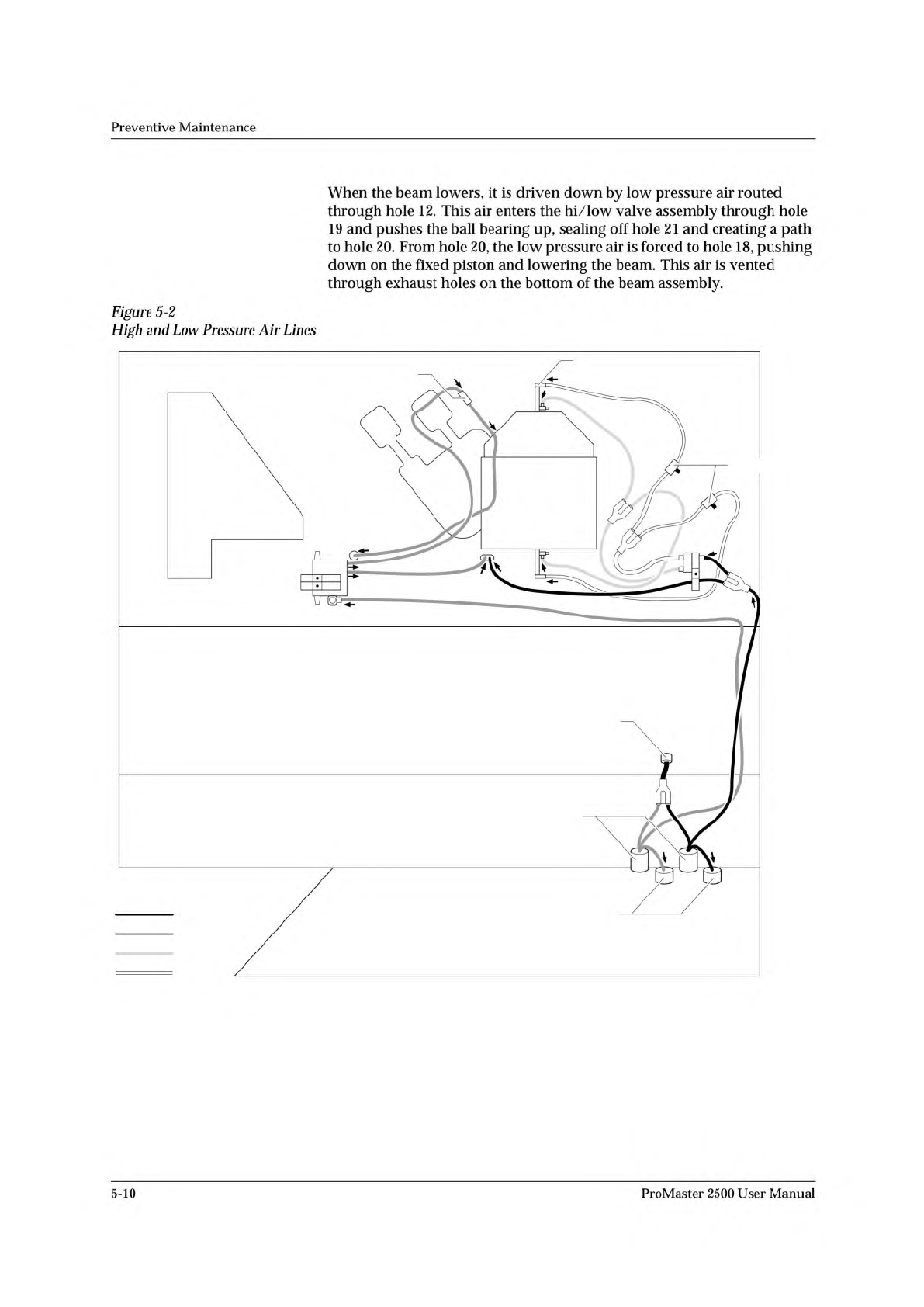
When
the
beam
lowers,
it
is
driven
down
by
low
pressure
air
routed
through
hole
12.
This
air
enters
the
hi/low
valve
assembly
through
hole
19
and
pushes
the
ball
bearing
up,
sealing
off
hole
21
and
creating
a
path
to
hole
20.
From
hole
20,
the
low
pressure
air
is
forced
to
hole
18,
pushing
down
on
the
fixed
piston
and
lowering
the
beam.
This
air
is
vented
through
exhaust
holes
on
the
bottom
of
the
beam
assembly.
Figure
5-2
High
and
Low
Pressure
Air
Lines
5-10
ProMaster
2500
User
Manual
16
17
4
5
18
20
21
19
11
12
17
18
21
20
19
2387-1
BEAM AIR
CYLINDER
Preventive
Maintenance
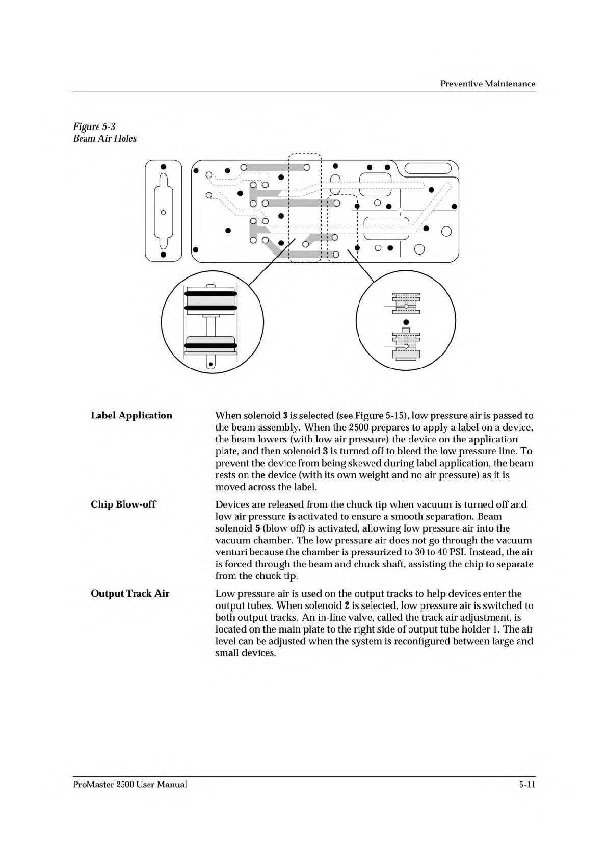
Figure
5-3
Label
Application
Chip
Blow-off
Output
Track
Air
When
solenoid
3
is
selected
(see
Figure
5-15),
low
pressure
air
is
passed
to
the
beam
assembly.
When
the
2500
prepares
to
apply
a
label
on
a
device,
the
beam
lowers
(with
low
air
pressure)
the
device
on
the
application
plate,
and
then
solenoid
3
is
turned
off
to
bleed
the
low
pressure
line.
To
prevent
the
device
from
being
skewed
during
label
application,
the
beam
rests
on
the
device
(with
its
own
weight
and
no
air
pressure)
as
it
is
moved
across
the
label.
Devices
are
released
from
the
chuck
tip
when
vacuum
is
turned
off
and
low
air
pressure
is
activated
to
ensure
a
smooth
separation.
Beam
solenoid
5
(blow
off)
is
activated,
allowing
low
pressure
air
into
the
vacuum
chamber.
The
low
pressure
air
does
not
go
through
the
vacuum
venturi
because
the
chamber
is
pressurized
to
30
to
40
PSI.
Instead,
the
air
is
forced
through
the
beam
and
chuck
shaft,
assisting
the
chip
to
separate
from
the
chuck
tip.
Low
pressure
air
is
used
on
the
output
tracks
to
help
devices
enter
the
output
tubes.
When
solenoid
2
is
selected,
low
pressure
air
is
switched
to
both
output
tracks.
An
in-line
valve,
called
the
track
air
adjustment,
is
located
on
the
main
plate
to
the
right
side
of
output
tube
holder
1.
The
air
level
can
be
adjusted
when
the
system
is
reconfigured
between
large
and
small
devices.
ProMaster
2500
User
Manual
5-11
Preventive
Maintenance
High
Air
Pressure
Beam
Programming
Module
Clamp
Assembly
High
pressure
air
is
routed
from
the
high
pressure
regulator
to
a
Y
connection
and
is
divided
into
beam
high
pressure
and
programming
module
clamp
assembly
air
pressure.
The
beam
high
pressure
air
is
routed
to
the
beam
by
a
black
air
line
that
passes
through
the
beam
and
into
a
straight-in
air
fitting
on
the
back
right
side
of
the
beam.
This
air
passes
two
milled-in
air
caps
(cavities),
which
dampen
air
spikes,
and
goes
to
solenoids
6
and
7,
mounted
to
the
left
center
of
the
beam.
Creating
the
Beam
Vacuum
The
beam
vacuum
required
to
hold
a
device
on
the
chuck
is
created
when
solenoid
7
(vacuum)
is
activated.
The
high
pressure
air
passes
through
the
beam
passes
through
the
top
hole
of
the
vacuum
venturi,
and
escapes
through
holes
in
the
bottom
of
the
beam.
As
this
rush
of
air
passes
the
venturi,
it
creates
a
vacuum
at
the
chuck
tip.
During
the
optics
test,
the
vacuum
value
should
fluctuate
between
about
26
(when
no
device
is
on
the
chuck)
and
172,
with
a
value
of
140
minimum
for
proper
vacuum.
The
vacuum
is
sensed
by
the
vacuum
sensor
(mounted
at
the
left
front
of
the
beam).
When
a
predefined
vacuum
level
is
detected
by
a
device
blocking
the
chuck
tip,
the
2500
assumes
that
the
beam
has
picked
up
a
device.
A
malfunction
of
the
vacuum
generator,
the
vacuum
sensor,
or
the
microswitch
can
cause
an
error
message
on
the
2500's
display
stating
that
the
beam
has
dropped
the
device
or
is
unable
to
pick
up
the
device.
Inserting
a
Device
into
the
Module
Low
pressure
air
lowers
the
beam
to
the
programming
module
contacts.
Additional
force
is
required
to
insert
the
device
into
the
programming
module.
Insertion
begins
when
the
high
pressure
air
present
at
hole
4
is
switched
to
hole
5
by
beam
solenoid
6
(high
pressure).
This
high
pressure
passes
to
hole
21,
pushing
the
ball
bearing
down
and
sealing
off
the
low
pressure
of
hole
19.
This
allows
high
pressure
to
pass
to
hole
20
and
enter
the
bottom
of
the
cylinder
at
hole
18.
Air
pushing
against
the
fixed
piston
pushes
the
beam
down
to
establish
the
required
continuity
between
the
devices
leads
and
the
module's
contacts.
Programming
module
clamp
assembly
air
is
switched
by
solenoid
8
to
either
open
the
clamps
(to
remove
a
module)
or
close
the
clamps
(to
hold
a
module
in
place).
Red
air
lines
carry
air
to
close
the
clamps;
blue
air
lines
carry
air
to
open
the
clamps.
In-line
valves
on
these
lines
control
the
amount
of
air
entering
the
air
cylinders
and
allow
ac^ustment
so
each
side
of
the
clamp
opens
and
closes
at
the
same
rate.
The
in-line
valves
for
the
red
lines
are
in
the
middle
of
the
air
lines,
while
the
valves
for
the
blue
lines
are
at
the
base
of
each
air
cylinder.
5-12
ProMaster
2500
User
Manual