2500_Users_Manual-.pdf - 第168页
MAIN PLATE (Underside) BACK OF BASE BOTTOM OF BASE FRONT OF BASE LABEL ADVANCE MOTOR PRINT HEAD P2 AC IN P1 TB2 TB1 J1 J2 J3 J4 240 220 120 100 J27 J22 J23 J24 J25 J24 J25 J3 J9 J10 J12 J1 3 J2 J11 * DISK DRIVE AC IN CON…
Preventive
Maintenance
The
Controller
Board
The
components
of
the
controller
board
are
listed
below.
•
LEDs
—
Used
for
a
quick
visual
check
on
the
status
of
various
power
supplies,
solenoids,
and
certain
logic
signals.
•
Connectors
—
Route
control
signals
to
optics,
microswitch,
motors,
solenoids,
and
other
components
of
the
handler.
•
Pico
fuses
—
12
for
the
stepper
motors
(two
per
stepper
driver
circuit
and
four
for
the
traverse
motor)
and
24
for
the
dot
matrix
print
head
wires
(one
fuse
for
each
wire
in
the
print
head).
Refer
to
the
schematic
in
Appendix
C
for
the
location
of
the
pico
fuses
associated
with
each
motor.
The
components
of
the
controller
board
supply
the
following:
•
Signals
to
activate
the
solenoids,
the
motors,
and
the
labeler
wires
•
Control
signals
for
the
two
RS-
232c
ports
and
the
handler
port
•
EPROM
that
contains
the
handler
system
firmware
•
EEPROM
that
stores
nonvolatile
handler
parameters
•
Circuitry
for
the
optics,
the
display,
and
the
keyboard
•
Microprocessor
and
kernel
logic
control
Refer
to
Appendix
C
for
the
controller
board
schematic
and
layout.
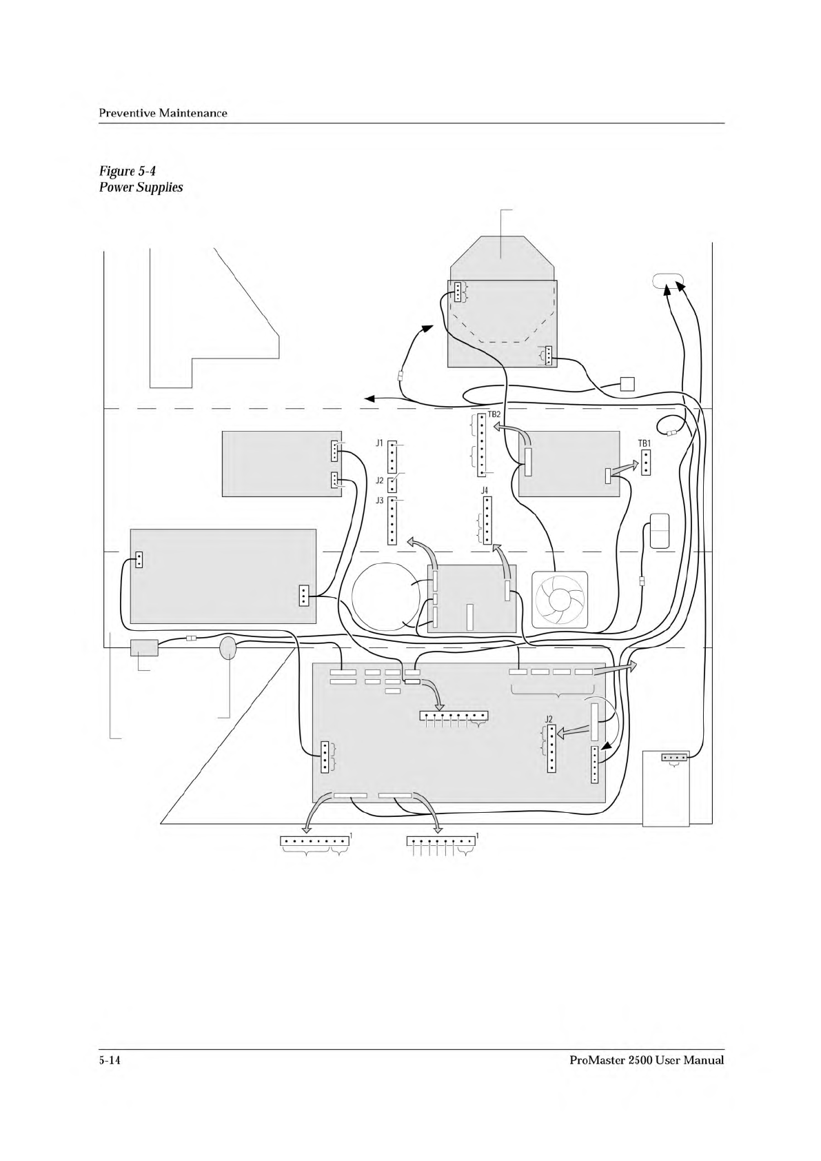
Power
Supplies
Four
power
supply
assemblies
are
located
in
the
body
of
the
2500.
See
Figure
5-4.
These
supplies
operate
off
the
handler's
single
AC
input.
•
Programming
Electronics
(PE)
Power
Supply:
PE
Controller/
Waveform
board
(+15V).
•
Labeler
Power
Supply:
Print
head
(+24V)
/solenoids
•
Toroid
Power
Supply:
•
Label
advance
motor
(+36V)
•
Input
orbital
motor
(+36V)
•
Output
orbital
motor
(+36V)
•
Beam
head
rotation
motor
(+36V)
•
Beam
traverse
motor
(+90V)
•
Controller
Board
Power
Supply:
Logic,
vacuum
generators,
sensor,
optics,
RS-
232c
ports,
and
the
2500's
display
(5V,
+/-12V).
ProMaster
2500
User
Manual
5-13
MAIN PLATE (Underside)
BACK OF BASE
BOTTOM OF BASE
FRONT OF BASE
LABEL
ADVANCE
MOTOR
PRINT HEAD
P2
AC IN P1
TB2
TB1
J1
J2
J3
J4
240
220
120
100
J27
J22
J23
J24 J25
J24 J25
J3
J9 J10 J12 J13
J2
J11
*
DISK
DRIVE
AC
IN
CONTROLLER
BOARD
POWER
SUPPLY
PROGRAMMING
ELECTRONICS
POWER SUPPLY
(TO BEAM)
SOLENOID
CLAMP
(TO SOLENOIDS
2 AND 3)
CONTROLLER
BOARD
PROGRAMMING ELECTRONICS
CONTROLLER BOARD
(TO BEAM
TRAVERSE
MOTOR)
MOTORS
**
* +90V on all six pins while motor is inactive.
** Approx. 16Vac (rms) while motor is running.
FAN
TORROID
POWER
SUPPLY
LABELER
POWER SUPPLY
2055-3
1
1
120V
GND
AC IN
GND
+24V
V1
+24V
+24V GND
+24V
NC
1
NC
+5V
GND
+12V
NC
-12V
NC
0
24
0
24
24
24
NC
1
1
1
120Vac
120Vac
97Vac
1
+15V
NC
+90V
GND
+90V
+36V GND
+36V
GND
NC
GND
120
+90V
GND
+90V
+36V GND
+36V
J10 - BEAM
ROTATE
MOTOR
J12 - INPUT
ORBITAL
MOTOR
J13 - OUTPUT
ORBITAL
MOTOR
GND
+15V
NC
GND
+15V
GND
NC
+5V
Preventive
Maintenance
Figure
5-4
Power
Supplies
5-14
ProMaster
2500
User
Manual
Preventive
Maintenance
Dot
Matrix
Label
Printer
The
dot
matrix
label
printer
(also
simply
referred
to
as
labeler)
uses
a
2
x
12-wire,
in-line
dot
matrix
print
head
to
print
labels.
The
labels
are
on
a
roll
of
label
liner
that
is
threaded
through
the
labeler
assembly
from
a
label
supply
reel.
The
labeler
can
print
a
maximum
of
three
lines
of
text
on
a
label.
The
label
drive
motor
is
the
second
motor
mounted
behind
the
labeler
assembly
plate.
It
provides
the
drive
to
turn
two
rollers
that
advance
the
liner
through
the
labeler
system.
The
black
pinch
roller
snaps
into
position
to
assist
the
label
advance
roller
to
get
a
firm
grip
on
the
label
liner.
The
timing
of
the
label
advance
roller
has
to
be
precise
so
it
can
accurately
place
the
label
on
the
device
and
ensure
even
spacing
between
the
printed
characters
on
the
label.
The
2500
lets
you
choose
the
position
of
the
label
on
the
device.
In
order
to
accomplish
this,
the
labeler
must
know
the
location
of
the
labels
on
the
liner
and
must
be
able
to
advance
the
label
so
it
contacts
the
device
at
the
correct
time.
On
the
front
of
the
labeler
assembly
plate,
the
ADC
optic
roller
assembly
detects
the
leading
edge
of
the
label.
The
highly
sensitive
ADC
optic
emitter/collector
pair
reads
the
level
of
light
that
passes
through
the
combined
label
and
liner
during
label
calibration.
This
light
reading,
called
the
ADC
optic
value,
is
the
reference
used
to
compare
to
the
higher
level
of
light
detected
when
only
the
liner
passes
through
the
optic.
This
reading
allows
the
labeler
to
synchronize
to
the
leading
edge
of
the
labels.
Character
Sizes
The
labeler
can
produce
six
font
sizes,
measured
in
characters
per
inch
(CPI).
The
six
font
sizes
are
listed
below.
•
Normal
Fonts:
18,
20,
and
26
CPI
•
Short
Font:
26
CPI
•
Tall
Fonts:
12,
16
ProMaster
2500
User
Manual
5-15