2500_Users_Manual-.pdf - 第172页
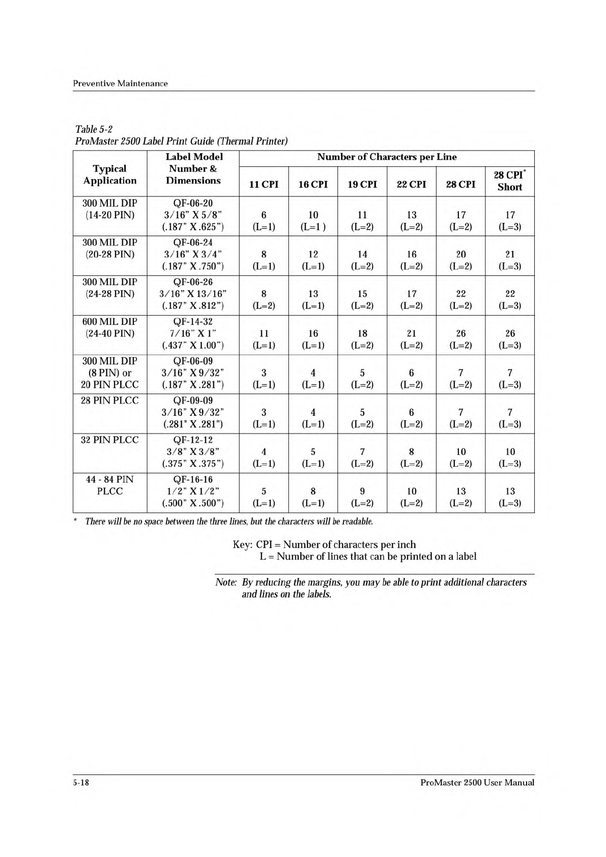
Preventive Maintenance Table 5-2 ProMaster 2500 Label Print Guide (Thermal Printer) There will be no space between the three lines, but the characters will be readable. Typical Application Label Model Number & Dimens…
Preventive
Maintenance
Thermal
Label
Printer
The
thermal
label
printer
(also
referred
to
simply
as
the
labeler)
uses
a
thermal
print
head
to
print
labels.
The
labels
are
supplied
on
a
roll
of
label
liner
that
is
threaded
through
the
labeler
assembly
from
a
label
supply
reel.
The
number
of
lines
that
the
labeler
can
print
on
a
label
is
determined
by
the
size
of
the
font
selected.
The
label
drive
motor
is
the
only
motor
mounted
behind
the
labeler
assembly
plate.
It
provides
the
drive
to
turn
two
rollers
that
advance
the
liner
through
the
labeler
system
as
well
as
two
rollers
that
advance
the
ribbon
through
the
labeler
system.
The
black
pinch
roller
snaps
into
position
to
assist
the
label
drive
roller
to
get
a
firm
grip
on
the
label
liner.
The
timing
of
the
label
advance
roller
has
to
be
precise
so
it
can
accurately
place
the
label
on
the
device
and
ensure
even
spacing
between
the
printed
characters
on
the
label.
The
2500
lets
you
choose
the
position
of
the
label
on
the
device.
In
order
to
accomplish
this,
the
labeler
must
know
the
location
of
the
labels
on
the
liner
and
must
be
able
to
advance
the
label
so
it
contacts
the
device
at
the
correct
time.
On
the
front
of
the
labeler
assembly
plate,
the
ADC
optic
detects
the
leading
edge
of
the
label.
The
highly
sensitive
ADC
optic
emitter/collector
pair
reads
the
level
of
light
that
passes
through
the
combined
label
and
liner
during
label
calibration.
This
light
reading,
called
the
ADC
optic
value,
is
the
reference
level
used
to
detect
the
increased
level
of
light
passing
through
the
liner
alone.
This
reading
allows
the
labeler
to
synchronize
with
the
leading
edge
of
the
labels.
Character
Sizes
The
labeler
can
produce
six
font
sizes,
measured
in
characters
per
inch
(CPI).
The
six
font
sizes
are
listed
below
(firmware
version
1.24
or
higher).
•
Normal
Fonts:
11,
16,
19,
22,
and
28
CPI
•
Short
Font:
28
CPI
ProMaster
2500
User
Manual
5-17
Preventive
Maintenance
Table
5-2
ProMaster
2500
Label
Print
Guide
(Thermal
Printer)
There
will
be
no
space
between
the
three
lines,
but
the
characters
will
be
readable.
Typical
Application
Label
Model
Number
&
Dimensions
Number
of
Characters
per
Line
11
CPI
16
CPI
19
CPI
22
CPI
28
CPI
28
CPI*
Short
300
MIL
DIP
(14-20
PIN)
QF-06-20
3/16”
X
5/8”
(.187”
X.
625”)
6
(L=l)
10
(L=l)
11
(L=2)
13
(L=2)
17
(L=2)
17
(L=3)
300
MIL
DIP
(20-28
PIN)
QF-06-24
3/16”
X
3/4”
(.187^^X.750^^)
8
(L=l)
12
(L=l)
14
(L=2)
16
(L=2)
20
(L=2)
21
(L=3)
300
MIL
DIP
(24-28
PIN)
QF-06-26
3/16”
X
13/16”
(.187”
X.
812”)
8
(L=2)
13
(L=l)
15
(L=2)
17
(L=2)
22
(L=2)
22
(L=3)
600
MIL
DIP
(24-40
PIN)
QF-14-32
7/16”
XI”
(.437”
X
LOO”)
11
(L=l)
16
(L=l)
18
(L=2)
21
(L=2)
26
(L=2)
26
(L=3)
300
MIL
DIP
(8
PIN)
or
20
PIN
PLCC
QF-06-09
3/16”
X
9/32”
(.187”
X.
281”)
3
(L=l)
4
(L=l)
5
(L=2)
6
(L=2)
7
(L=2)
7
(L=3)
28
PIN
PLCC
QF-09-09
3/16”
X
9/32”
(.281"
X
.281")
3
(L=l)
4
(L=l)
5
(L=2)
6
(L=2)
7
(L=2)
7
(L=3)
32
PIN
PLCC
QF-12-12
3/8”
X
3/8”
(.375”
X.
375”)
4
(L=l)
5
(L=l)
7
(L=2)
8
(L=2)
10
(L=2)
10
(L=3)
44
-
84
PIN
PLCC
QF-16-16
1/2”
X
1/2”
(.500^^X.500^^)
5
(L=l)
8
(L=l)
9
(L=2)
10
(L=2)
13
(L=2)
13
(L=3)
Key:
CPI
=
Number
of
characters
per
inch
L
=
Number
of
lines
that
can
be
printed
on
a
label
Note:
By
reducing
the
margins,
you
may
be
able
to
print
additional
characters
and
lines
on
the
labels.
5-18
ProMaster
2500
User
Manual
Preventive
Maintenance
Programming
Electronics
Boards
and
Assemblies
The
PE
is
composed
of
two
main
units
that
are
mounted
on
the
underside
of
the
handler's
main
plate
at
the
programming
station.
The
PE's
major
assemblies
are
described
in
the
following
section.
•
Power
Supply
—
The
input
AC
generates
+15V
DC
that
is
routed
to
the
controller/waveform
board's
internal
power
supply
circuits.
•
Controller/waveform
Board
—
Uses
+15V
(from
the
power
supply)
to
generate
a
precise
+10V
reference.
This
reference
acts
as
an
input
to
12-bit
DACs
that
help
generate
numerous
voltages
(+/-
5V
DC,
+/-
8V
DC,
+10V
REF,
+13V
DC,
-15V
DC,
+25V
DC,
and
+36V
DC)
for
use
primarily
on
the
pin
driver
board
(s).
The
center
of
the
controller
circuitry
is
a
68000
microprocessor
that
controls
system
operation
using
64K
of
Flash
EPROM,
system
RAM,
and
8
MB
of
user
RAM.
Two
RS-
232c
ports
are
located
on
this
board
and
use
the
PE's
SmartPort
software
feature
to
toggle
the
cables
DTE
and
DCE
lines
until
a
connection
is
established.
The
floppy
disk
controller
provides
the
signal
interface
between
the
main
system
and
the
disk
drive.
A
special
circuit
called
the
pin
control
unit
(PCU)
acts
as
a
coprocessor
that
controls
read/write
and
timing
signals
to
the
pin
driver
boards.
A
68-pin
and
a
50-pin
cable
carry
control
signals
and
supply
voltages
from
the
control
unit
base
to
the
pin
driver
board
(s).
•
Mass
Storage
Module
(MSM)
—
The
internal
hard
drive.
Under
the
default
configuration
for
the
2500,
algorithm
files
are
automatically
installed
on
the
MSM
when
you
update
system
software.
The
MSM
is
partitioned
into
4
logical
drives:
•
User
data
drives
C
and
D:
31MB
and
512
maximum
files
each.
•
System
data
drives
H
and
I:
7MB
and
10MB
respectively
with
320
maximum
files
each.
Reserved
for
operating
system
files.
•
Disk
Drive
—
Double-sided,
quad-density
(1.44
MB
formatted),
3.5-
inch
disk
drive
reads
the
PE
system
disk
to
load
updated
commands
into
system
RAM
and
the
MSM.
It
can
also
be
used
to
load
data
flies
into
user
RAM.
•
Relay
Board
—
Controls
the
flow
of
signals
between
the
controller/
waveform
board
and
the
pin
driver
board
(s).
Cables
from
the
controller
unit
connect
to
the
pin
driver
head
through
the
relay
board.
These
signals
are
routed
to
the
pin
driver
board(s)
and
then
through
the
relay
board
to
the
device
to
be
programmed.
Relays
on
this
board
are
energized
to
provide
hard
V^c
and
GND
levels
to
device
pins
as
required
by
the
programming
algorithm.
ProMaster
2500
User
Manual
5-19