2500_Users_Manual-.pdf - 第175页
Preventive Maintenance TaskLink also allows you to download device data from a file on your PC. TaskLink sends the PE information on the data file format and then downloads the file. The PE translates the formatting info…
Preventive
Maintenance
Self-calibration
Programming
Devices
•
Pin
Driver
Board
(s)
—
Internally
generated
supply
voltages
serve
as
inputs
to
the
pin
driver
circuits
from
the
waveform
section
of
the
controller
/waveform
board.
Control
signals
from
the
PCU
coprocessor
on
the
controller/waveform
board
are
also
received
and
used
by
the
pin
driver
circuitry
on
the
board
to
shape
programming
waveforms.
The
pin
driver
controls
the
signal
slew
rates,
current
source,
and
voltage
levels
required
to
provide
precise
programming
signals
to
the
device
installed
in
the
programming
module.
These
signals
are
routed
through
the
relay
board
to
the
SPA
block
and
then
to
the
device.
•
Squirt
Pin
Assembly
(SPA
Block)
—
This
assembly
has
no
active
circuitry
but
provides
the
shortest
possible
signal
path
between
the
signal
source
and
the
device
installed
in
the
programming
module.
•
Programming
Modules
—
Act
as
the
interface
between
the
device
to
be
tested/programmed
and
the
PE.
Modules
are
available
for
300-
and
600-mil.
(0.300-inch
and
0.600-inch
wide)
DIP
devices;
20-,
28-,
32-,
44-,
52-,
68-,
and
84-pin
PLCC
devices;
and
150-,
300-,
400-,
and
500-mil
SOIC
devices.
DIP
modules
use
high
quality
contact
sets
to
establish
contact
with
the
device
pins.
PLCC
devices
are
inserted
into
a
self-funneling
programming
block
to
achieve
correct
alignment.
The
PE
Device
List
disk
(included
in
each
update
kit)
lists
the
supported
devices
and
which
programming
module
to
use
for
a
specific
device.
The
PE
performs
an
automatic
self-calibration
of
its
supplies
each
time
the
programmer
is
powered
up
and
the
self-test
is
run.
The
internal
power
supply
outputs
+15V
DC
to
the
waveform
section
of
the
controller/waveform
board.
This
acts
as
the
input
to
a
precision
voltage
regulator
that
outputs
a
+10V
REF
supply.
This
REF
supply
is
used
as
the
input
to
digital-to-analog
converter
(D
AC)
controlled
voltage
and
current
source
circuits
on
the
waveform
board.
One
DAC
outputs
a
comparator
reference
(Comp
Ref)
voltage
and
the
+10V
REF
supply
is
used
to
confirm
that
the
DAC
output
is
correct.
The
Comp
Ref
voltage
is
used,
in
turn,
to
verify
the
correct
output
voltage
levels
of
other
supplies
on
the
board.
Additional
comparator
reference
levels
are
used
on
the
pin
driver
board
to
confirm
the
output
voltages
as
they
appear
at
the
programming
module.
Overcurrent
detection
circuitry
is
also
tested
during
self-calibration.
Waveform
timing
is
derived
from
a
crystal-controlled
programmable
clock,
which
is
driven
off
the
main
system
clock.
The
PE
responds
to
computer
remote
control
commands
issued
by
TaskLink,
running
on
the
PC.
Data
to
be
programmed
into
a
device
is
usually
loaded
from
a
master
device
or
from
a
file.
When
a
master
device
is
selected,
the
handler
inserts
the
device
into
the
programming
module,
then
the
PE
reads
that
data
through
the
programming
module
contacts,
SPA
pins,
and
pin
drivers.
Device
data
is
stored
in
user
RAM
on
the
controller/waveform
board
as
an
image
of
the
fuses
in
the
device.
This
RAM
data
is
preserved
until
a
new
device
is
loaded,
RAM
is
changed
by
the
user,
or
the
programmer
is
powered
down.
5-20
ProMaster
2500
User
Manual
Preventive
Maintenance
TaskLink
also
allows
you
to
download
device
data
from
a
file
on
your
PC.
TaskLink
sends
the
PE
information
on
the
data
file
format
and
then
downloads
the
file.
The
PE
translates
the
formatting
information
in
the
file,
discards
all
formatting
characters
and
stores
the
data
in
RAM.
The
PE
signals
TaskLink
when
it
completes
writing
the
file
data
into
RAM.
TaskLink
then
sends
the
“program”
command
to
the
PE
and
the
device
is
programmed.
Conditions
Requiring
Corrective
Action
To
run
the
diagnostic
tests
and
to
make
some
of
the
adjustments,
you
must
operate
the
2500
from
its
front
panel
in
local
mode.
You
cannot
run
the
tests
using
TaskLink.
To
access
the
front
panel
from
remote
mode,
press
LOWER
CASE
+
L.
To
return
to
remote
mode
after
completing
the
diagnostics
and
adjustments,
press
LOWER
CASE
十
R
from
the
Main
Menu.
Device
Jams
The
optics
detect
stopped
or
jammed
devices
and
alert
you
to
the
condition.
Some
common
causes
for
device
jams
are
listed
below.
•
The
track
width
is
not
adjusted
correctly
for
the
device
in
the
track.
•
A
partially
full
output
tube
was
inserted
in
the
tube
holder.
TaskLink
assumed
the
tube
was
empty
and
sent
too
many
devices
to
the
tube.
•
The
number
of
parts
per
tube
is
incorrect.
•
The
track
is
dirty
so
devices
cannot
travel
smoothly.
•
A
device
has
bent
leads
that
cause
it
to
become
wedged
in
the
narrow
track.
•
A
device
has
foreign
material
(such
as
residual
label
adhesive)
on
the
surface.
•
The
output
track
air
pressure
is
set
too
low
for
the
size
of
the
device.
•
The
transition
height
between
the
output
tracks
and
the
tubes
is
incorrect.
Adjust
the
output
transition
height
screw
(for
the
affected
track)
for
the
correct
tube
thickness.
If
a
jam
occurs
in
the
output
track
and
the
2500
stops
operating,
push
the
jammed
device
with
a
wood
or
plastic
pointer
into
the
tube.
When
you
free
the
device,
either
the
2500
resumes
operation
automatically
or
you
may
need
to
press
START
to
continue
operation.
If
a
device
does
not
move
easily
down
the
input
track
due
to
bent
pins
or
some
other
condition,
you
might
have
to
remove
that
device
from
the
input
track
and
resume
operation
by
pressing
START
or
by
restarting
the
Task.
If
a
device
falls
off
the
chuck,
replace
it,
press
START
and
follow
the
prompts
on
the
2500's
display.
If
the
system
times
out,
press
STOP
and
then
START.
ProMaster
2500
User
Manual
5-21
1591-1
Preventive
Maintenance
Faulty
Printing
Printing
Is
Too
Light
The
ribbon
is
worn
or
broken,
the
print
head
is
worn,
or
the
print
head
gap
is
too
great.
Replace
ribbon,
or
print
head.
Adjust
the
print
head
gap
(see
page
5-24).
Characters
Too
Close
Together
Labels
are
loaded
incorrectly,
the
rollers
are
dirty,
or
the
motor
or
drive
circuitry
is
not
operating
properly.
Load
the
labels
correctly,
clean
the
rollers,
and
make
sure
the
pinch
rollers
are
engaged
(see
page
2-9).
Check
the
label
advance
motor;
run
motor
diagnostics.
Print
Is
Erratic
or
Slanting
Print
head
gap
is
too
great,
or
the
label
drive
is
slipping.
Check
and
adjust
the
print
head
gap
(see
page
5-24),
or
clean
the
label
rollers.
Dots
in
Characters
Are
Missing
The
cables
may
not
be
properly
connected
or
they
may
be
faulty.
The
print
head
or
handler
controller
board
may
not
be
operating
properly.
The
labeler
power
supply
may
not
be
at
the
correct
voltage
level.
Check
the
power
supply
voltage
switch.
If
problem
persists,
contact
Data
I/O
Support
(phone
numbers
listed
in
the
Preface).
Check
the
LEDs
on
the
handler
controller
board
and
evaluate
the
labeler
operation
by
running
the
print
test.
Check
the
cable
connections.
Swap
cables
and
see
if
different
dots
are
missing.
Replace
the
print
head
(see
page
7-13).
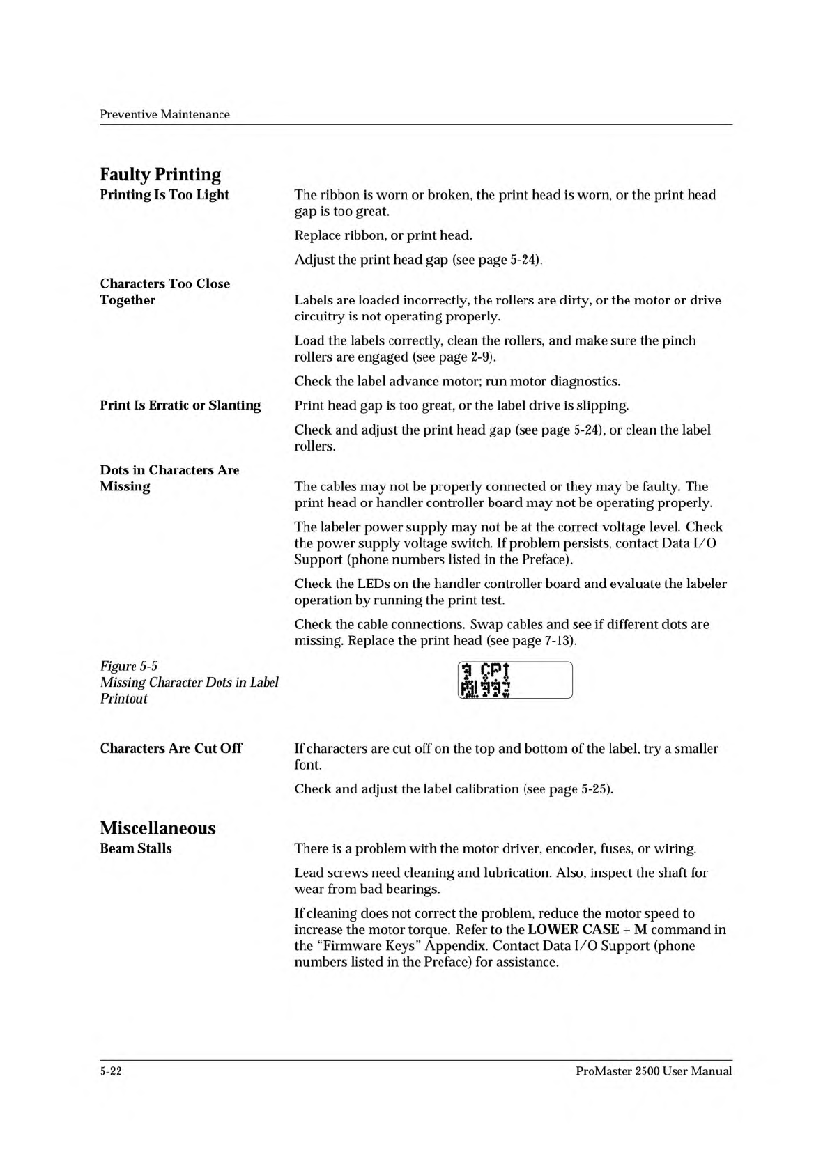
Figure
5-5
Missing
Character
Dots
in
Label
Printout
KI
Characters
Are
Cut
Off
If
characters
are
cut
off
on
the
top
and
bottom
of
the
label,
try
a
smaller
font.
Check
and
adjust
the
label
calibration
(see
page
5-25).
Miscellaneous
Beam
Stalls
There
is
a
problem
with
the
motor
driver,
encoder,
fuses,
or
wiring.
Lead
screws
need
cleaning
and
lubrication.
Also,
inspect
the
shaft
for
wear
from
bad
bearings.
If
cleaning
does
not
correct
the
problem,
reduce
the
motor
speed
to
increase
the
motor
torque.
Refer
to
the
LOWER
CASE
+
M
command
in
the
“Firmware
Keys”
Appendix.
Contact
Data
I/O
Support
(phone
numbers
listed
in
the
Preface)
for
assistance.
5-22
ProMaster
2500
User
Manual