2500_Users_Manual-.pdf - 第182页
Preventive Maintenance 5. If necessary, remove the two screws that hold the guard in place. Loosen the collar and remove the ribbon drive roller assembly from the printer. Hold the roller with one hand and turn it with t…
↑ ↓
PROGRAM/TEST LABEL
SLAVE MODE PART TYPE: DIP 24-.3
PART TOTAL: 251 PART LENGTH: 1.250
LABEL CAL: (XXX)
Preventive
Maintenance
Label
Calibration
Label
Advance
Adjusting
the
Thermal
Printer
Change
the
label
calibration
value
using
the
STOP
command
described
in
the
following
procedure.
1.
Press
STOP
to
pause
the
2500
while
a
Task
is
running.
2.
Press
LOWER
CASE
+
C.
The
2500
displays:
where
XXX
represents
a
numeric
value
for
the
current
setting.
3.
Press
or
to
change
the
label
calibration
value
(the
range
is
from
0
to
255).
Entering
a
larger
numeric
value
moves
the
printed
characters
closer
to
the
leading
edge
of
the
label.
4.
Press
START
to
continue
running
the
Task.
The
label
advance
value
defines
how
far
a
label
is
extended
above
the
application
plate
just
before
it
is
applied
to
a
device
(see
Figure
5-14).
The
value
can
be
changed
by
pressing
STOP
and
LOWER
CASE
+
W.
Increasing
the
numeric
value
advances
the
label
farther
above
the
application
plate.
When
the
thermal
printer
is
operating
correctly,
the
label
and
ribbon
material
advance
smoothly
and
without
any
binding
or
excess
slack.
If
any
of
the
clutches
that
are
attached
to
the
rollers
begin
to
bind,
they
can
cause
the
feeding
and
advancing
of
both
label
and
ribbon
material
to
go
out
of
adjustment.
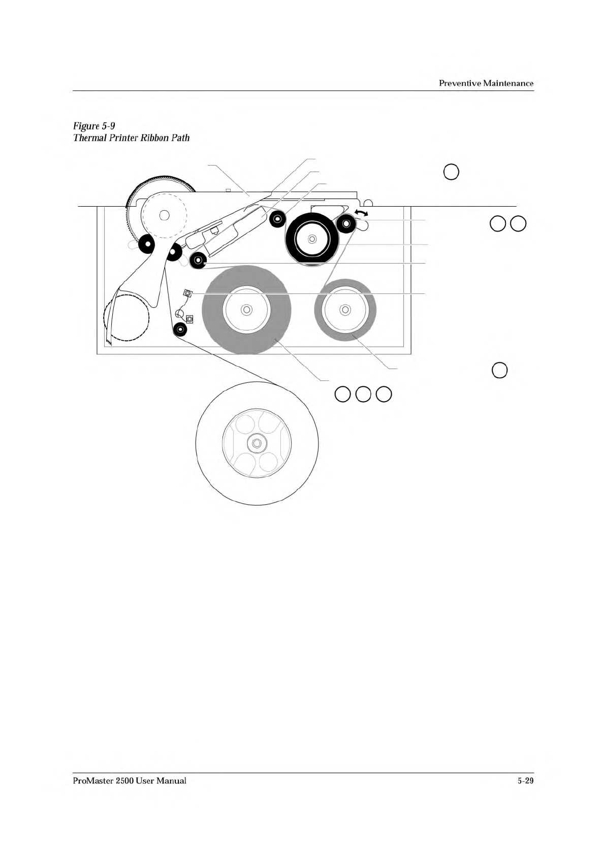
To
adjust
the
thermal
printer,
follow
these
steps
(see
Figure
5-9):
1.
Starting
with
the
ribbon
(supply)
roll
hub,
check
that
it
has
only
slight
friction.
Remove
the
ribbon
hub
and
spring
washer.
2.
Hold
the
spring
washer
in
your
hand
and,
using
small
needlenose
pliers,
bend
the
three
fingers
so
they
produce
less
(or
more,
if
required)
friction
on
the
hub.
3.
Reinstall
the
spring
washer
and
hub
on
the
printer.
Check
that
there
is
now
only
slight
friction.
4.
Print
a
label
and
observe
the
amount
of
slack
in
the
ribbon
when
the
printer
head
pivots
up
to
print.
The
ribbon
should
droop
down
about
3/4”
when
the
print
head
pivots
up.
If
it
does
not,
loosen
the
lock
nut
on
the
damper
at
the
top
of
the
air
cylinder
using
small
needlenose
pliers,
and
adjust
it
counterclockwise
with
a
small
flat-
blade
screwdriver
until
the
head
pivots
up
fast
enough
to
create
the
droop.
Then
tighten
the
lock
nut
with
the
small
needlenose
pliers.
ProMaster
2500
User
Manual
5-27
Preventive
Maintenance
5.
If
necessary,
remove
the
two
screws
that
hold
the
guard
in
place.
Loosen
the
collar
and
remove
the
ribbon
drive
roller
assembly
from
the
printer.
Hold
the
roller
with
one
hand
and
turn
it
with
the
other.
If
more
than
a
small
amount
of
friction
is
felt,
adjust
the
collar
counterclockwise
until
only
a
slight
amount
of
friction
is
felt.
Note:
If
the
ribbon
drive
roller
assembly
has
a
Belleville
washer
rather
than
a
finger
spring
washer
(Part
Number
265-4485-901),
让
should
be
replaced
with
the
finger
spring
washer,
fingers
out,
fb〃owed
by
the
washer,
and
finally
the
collar,
which
allows
for
a
greater
range
of
adjustment.
6.
Install
the
adjusted
ribbon
drive
roller
assembly
by
sliding
the
complete
assembly
onto
the
shaft.
Hold
the
assembly
in
place
with
your
index
finger
on
the
center
of
the
drive
pulley
and
thumb
on
the
ribbon
drive
roller,
and
tighten
the
collar
with
the
assembly
held
in.
You
might
have
to
hold
the
back
side
of
the
clutch
so
the
shaft
does
not
slide
back.
Note:
The
collar
tightens
most
easily
and
securely
when
the
slots
on
the
collar
are
aligned
with
the
slots
on
the
ribbon
drive
roller.
7.
Install
the
guard
and
check
to
make
sure
the
ribbon
drive
roller
is
not
dragging
against
the
guard.
If
the
roller
contacts
the
guard,
shim
the
guard
out
slightly
using
one
or
more
flat
washers.
8.
Check
the
take-up
roller.
It
should
have
only
slight
friction.
Then
adjust
the
clutch
on
the
shaft
on
the
inside
of
the
printer,
if
needed.
9.
To
check
the
adjustment,
run
PRINT
ONLY
mode
and
make
sure
all
of
the
following
are
true:
•
Print
quality
is
good
(crisp,
clear,
legible,
and
properly
aligned).
•
Ribbon
does
not
get
caught
in
the
application
area.
•
Ribbon
takes
up
properly.
•
Ribbon
does
not
move
during
calibration.
5-28
ProMaster
2500
User
Manual
2304-2
PRINT HEAD (Retracted position)
RIBBON ALIGNMENT ROLLER 2
RIBBON ALIGNMENT
ROLLER 1
RIBBON DETECT OPTIC
RIBBON ROLL
RIBBON PINCH
ROLLER
RIBBON DRIVE ROLLER
PLATEN
RIBBON TAKE-UP ROLL
APPLICATION AREA
1 2 3
4
5 6
8
Figure
5-9
Thermal
Printer
Ribbon
Path
Preventive
Maintenance
ProMaster
2500
User
Manual
5-29